©2004 Sony Corporation Printed in China
El VCT-1500L es un trípode para
cámaras digitales/videocámaras.
La sección inferior puede quitarse
para permitir una gama completa
creatividad con solamente 180 mm
No lleve nunca el trípode con la
cámara digital/videocámara
•Limpie el trípode con un paño
suave ligeramente humedecido en
una solución de detergente suave.
•Después de haber utilizado el
trípode en un lugar sometido a la
brisa del mar, cerciórese de
limpiarlo frotándolo con un paño
(Patas desplegadas y elevador
El diseño y las especificaciones
están sujetos a cambio sin previo
Con respecto a los detalles de cada
2Zapata para montaje de la
5Perilla de ajuste de montaje a
10 Tornillo y perilla de montaje
11 Palanca de bloqueo de la
zapata para montaje de la
12 Perilla de bloqueo de la
15 Palanca de bloqueo del ajuste
1Desbloquee las palancas de
2Ajuste la longitud de las
4Separe las patas hasta que el
Extienda las patas del trípode
lentamente y con cuidado.
Si las separase a la fuerza podría
Instale la batería, un “Memory
Stick”, y un videocasete en la
cámara digital/videocámara antes
de montarla en el trípode.
1Tirando de la palanca de
bloqueo de la zapata para
“FREE”, deslice y quite la
zapata para montaje de la
2Fije la zapata para montaje de
la cámara a la cámara digital/
Cuando fije la videocámara,
3Tirando de la palanca de
bloqueo de la zapata para
trípode. Después, empuje la
zapata para montaje de la
1Afloje la perilla de bloqueo
2Ajuste la altura moviendo la
3Apriete la perilla de bloqueo
El mango de panorámica de este
trípode permite el bloqueo de
panorámica y el bloqueo de picado.
Si aprieta ligeramente el mango de
panorámica, podrá bloquear el
picado, y si lo aprieta más, podrá
Antes de utilizar las funciones de
panorámica y picado, cerciórese de
que el elevador esté firmemente
bloqueado con la perilla de bloqueo
desbloqueado, la cámara digital/
videocámara podría sufrir
2Ajuste la posición moviendo
三脚の脚はゆっくりと開いてください。強い力で引っ張ると故障の原因に
バッテリーやメモリースティック、カセットは、デジタルスチルカメラ
/ビデオカメラを三脚に取り付ける前にセットしておいてください。
2クイックシューをデジタルスチルカメラ/ビデオカメラに取り付け
ビデオカメラを取り付ける際には、ビデオボスをボス穴に合わせてく
2カメラ台を上下にを動かし、適当な高さに合わせる。
この三脚はパンハンドル1本で、パンロック/ティルトロックができま
す。パンハンドルを軽く締めるとティルトロックになり、そこからさらに
エレベーターストッパーがしっかり締まっているか確認してから、パンニ
ング/ティルティングは行ってください。締めかたが充分でないと、画像
2パンハンドルを左右方向の希望の位置に動かし調節する。
この三脚はローポジション対応のため、エレベーターが
げ、パンロックした状態で反時計回りにパンニングしつづけると、エレ
ベーターBからエレベーターAがはずれます。エレベーターを上げてパ
ンニングするときは、エレベーターAとエレベーターBをしっかり締
デジタルスチルカメラ/ビデオカメラを上下に動かして撮影することがで
5パンハンドルを上下方向の希望の位置に動かし調節する。
6パンハンドルを締めて固定する。(ティルトロック)
2開脚調整ノブをカチッと止まるまで右方向へスライドさせる。
ローポジションで下から上に向けて撮影をする場合は、デジタルス
チルカメラ/ビデオカメラを前後逆に取り付けると撮影することが
2ローポジションの状態から、開脚調整ノブが自動的にカチッと左方向
ローポジションとセミローポジションでご使用になられるときは、脚をの
ばすと、強度が充分取れませんので、脚はのばさないでご使用ください。
この製品には保証書が添付されていますので、お買い上げの際、お受け
所定事項の記入および記載内容をお確かめのうえ、大切に保存してくだ
この取扱説明書をもう一度ご覧になってお調べください。
保証書の記載内容に基づいて修理させていただきます。詳しくは保証書を
修理によって機能が維持できる場合は、ご要望により有償修理させていた
This equipment has been tested and
found to comply with the limits for
a Class B digital device, pursuant to
Part 15 of the FCC Rules. These
limits are designed to provide
reasonable protection against
harmful interference in a residential
installation. This equipment
generates, uses, and can radiate
radio frequency energy and, if not
installed and used in accordance
with the instructions, may cause
harmful interference to radio
communications. However, there is
no guarantee that interference will
not occur in a particular
installation. If this equipment does
cause harmful interference to radio
or television reception, which can
be determined by turning the
equipment off and on, the user is
encouraged to try to correct the
interference by one or more of the
– Reorient or relocate the receiving
– Increase the separation between
the equipment and receiver.
– Connect the equipment into an
outlet on a circuit different from
that to which the receiver is
– Consult the dealer or an
experienced radio/TV technician
You are cautioned that any changes
or modifications not expressly
approved in this manual could void
your authority to operate this
Directive: EMC Directive 89/336/
This equipment complies with the
EMC regulations when used under
the following circumstances:
(This equipment complies with the
EMC standard regulations EN55022
The VCT-1500L is a tripod for
digital still cameras/video cameras.
Lower section can be detached to
allow full range of use. Allows for
more creativity only 7 inches from
Never carry the tripod with the
digital still camera/video camera
•Clean the tripod with a soft cloth
lightly moistened with a mild
•After using the tripod at a location
subject to sea breezes, be sure to
wipe it clean with a dry cloth.
Approx. 430 mm (17 inches)
Set of printed documentation
Design and specifications are
subject to change without notice.
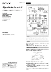
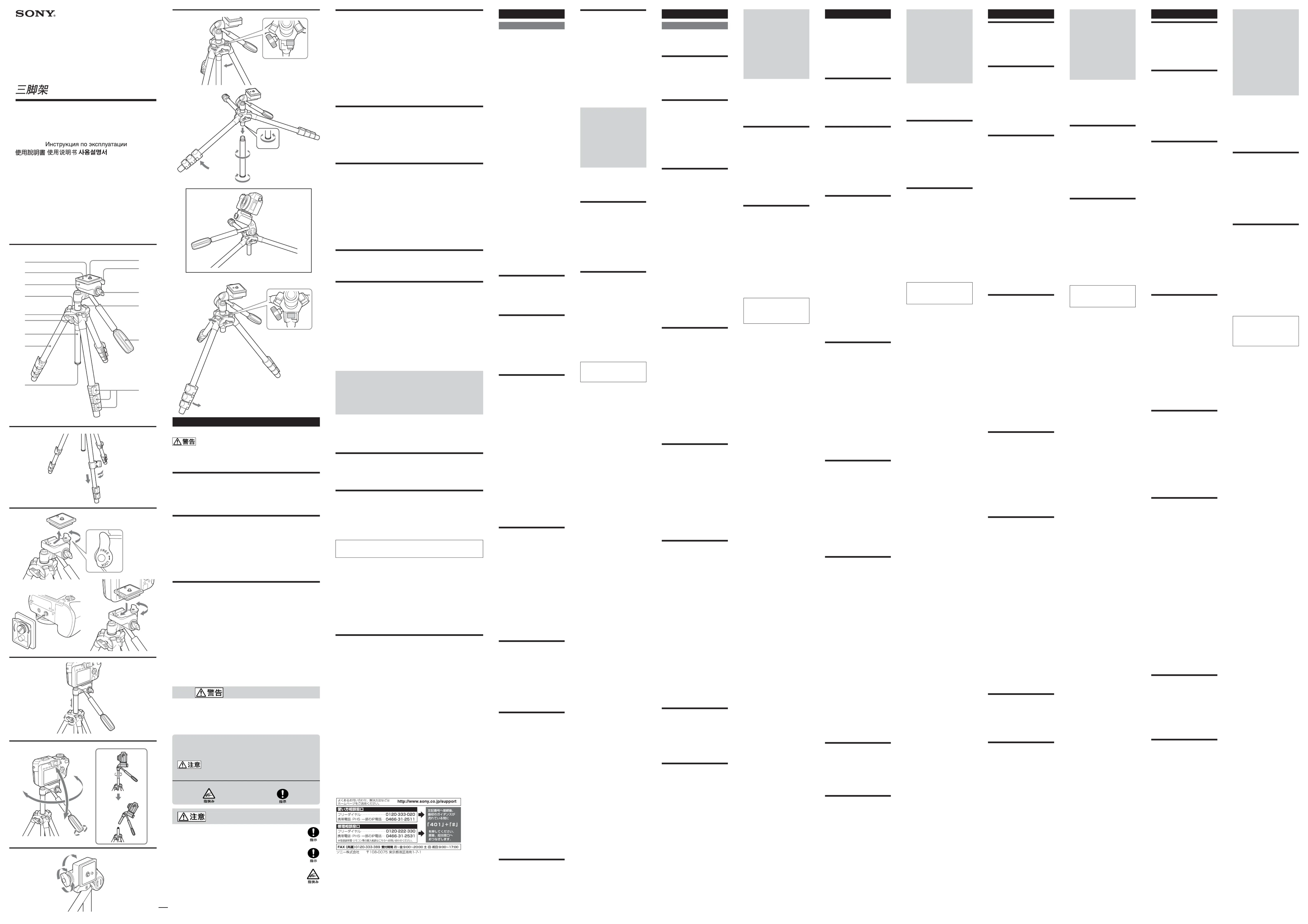
Refer to A to G for details of
5Straddle adjustment knob
10 Camera mounting screw and
11 Camera mounting shoe lock
15 Leg length adjustment lock
2Adjust the length of the legs.
4Spread the legs until the
Spread the tripod legs slowly and
Pulling them apart forcefully may
Install the battery pack, “Memory
Stick” and a cassette in the digital
still camera/video camera before
1While pulling the camera
fully to “FREE”, slide out the
camera mounting shoe from
2Attach the camera mounting
shoe to the digital sitll
Tighten the screw firmly.
When you attach the video
camera, align the pin with the
3While pulling the camera
fully to “FREE”, replace the
camera mounting shoe with
the camera attached into the
tripod head. Then, push the
camera mounting shoe lock
This tripod’s one pan handle
provides both pan lock and tilt lock.
Fastening the pan handle lightly
enables tilt lock, and fastening it
tighter enables pan lock.
Before panning and tilting, make
sure that the elevator lock knob is
locked firmly. If it is unlocked, it
will cause a digital sitll camera/
3Tighten the pan handle. (Pan
This tripod has two separate
elevators for low position work.
If you raise the connection part
of elevator A and elevator B
from the main unit and keep
during pan lock, elevator A will
come apart from elevator B.
When panning with the elevator
raised, fasten elevator A and
elevator B tightly and be sure to
6Tighten the pan handle. (Tilt
The horizontal shooting position
can be changed to the vertical
1Loosen the tripod head lock
2Stand the tripod head to the
3Tighten the tripod head lock
Low position (illustration A)
2Slide the straddle adjustment
knob towards the right until
5Remove the elevator stopper
screw from elevator B, then
attach the elevator stopper
screw to the connection part
*2 You can shoot upwards from
a low position by attaching
the digital still camera to the
Semi-low position (illustration
2From the low position, close
the legs so that the straddle
adjustment knob slides to the
left and automatically clicks
This is the semi-low position.
1Close the legs and then open
2If elevator B is unattached,
attach it to the connection
Do not extend the legs in the low
position or semi-low position. The
legs are not strong enough when
この取扱説明書には、事故を防ぐための重要な注意事項と製品の取り扱いかたを示し
ています。 製品を安全にお使いください。お読この取扱説明書をよくお読みのうえ、
みになったあとは、いつでも見られるところに必ず保管してください。
この三脚はデジタルスチルカメラ/ビデオカメラなどにお使いいただけま
デジタルスチルカメラ/ビデオカメラを取り付けたままで、持ち歩かない
汚れたら、やわらかい布に中性洗剤溶液を含ませて拭いてから、乾いた
海岸など、潮風の当たる所で使用したあとは、乾いた布でよく拭いてく
仕様および外観は、改良のため予告なく変更することがあります。
ソニー製品は安全に充分配慮して設計されています。しかし、まちがった
使いかたをすると、人身事故になることがあり危険です。事故を防ぐため
取扱説明書では、次のような表示をしています。表示の内容をよく理解
この表示の注意事項を守らないと、感電やその他の事故
によりけがをしたり周辺の家財に損害を与えたりするこ
下記の注意事項を守らないと、 をすることがありけが
制限重量を超えると、三脚が倒れたりしてけがの原因となることが
開脚してからデジタルスチルカメラ/ビデオカメラを取り付ける
脚を閉じたまま取り付けると、転倒してデジタルスチルカメラ/ビ
デオカメラを破損したりけがの原因となることがあります。
脚の出し入れ、エレベーターの操作には充分注意をはらう
Toute modification ou tout
expressément dans ce manuel peut
conduire à l’interdiction de l’emploi
Le VCT-1500L est un trépied pour
appareils photo/caméscopes
La partie inférieure peut être
détachée pour un emploi plus varié.
Offre plus de possibilités à 7 pouces
Ne jamais transporter le trépied par
l’appareil photo ou le caméscope
•Nettoyez le trépied avec un
•Si vous avez utilisé le trépied à un
endroit exposé aux embruns
marins, essuyez-le bien avec un
chiffon sec avant de le ranger.
Angle de panoramique vertical
Appro. 1 500 mm (59 1/8 pouces)
(avec pieds écartés et élévateur)
Approx. 430 mm (17 pouces)
Jeu de documents imprimés
La conception et les spécifications
peuvent être modifiées sans avis
Voir A à G pour le détail.
10 Vis et molette de montage
11 Levier de verrouillage de
12 Molette de verrouillage de la
14 Poignée de panoramique
15 Leviers de verrouillage du
réglage de la longueur des
1Débloquez les leviers de
verrouillage du réglage de la
3Rebloquez les leviers de
verrouillage du réglage de la
4Ecartez les pieds jusqu’à ce
que le trépied soit stable.
Étirez les pieds du trépied
doucement et avec précaution.
Ne pas forcer pour ne pas les
Installez la batterie, un « Memory
Stick » et une cassette dans
l’appareil photo/caméscope
numérique avant de le visser sur le
1Tout en tirant le levier de
montage complètement vers
« FREE », détachez le sabot
2Fixez le sabot de montage à
l’appareil photo/caméscope
caméscope, alignez la broche
3Tout en tirant le levier de
remettez le sabot de montage
avec le caméscope dans la
montage vers « LOCK » pour
verrouillage de l’élévateur.
bougeant la tête de trépied.
verrouillage de l’élévateur.
Le verrouillage du panoramique
horizontal et le verrouillage du
panoramique vertical s’effectuent
avec la poignée de panoramique.
La poignée de panoramique doit
être serrée légèrement pour le
verrouillage du panoramique
vertical et plus fort pour le
verrouillage du panoramique
Avant de faire un panoramique
horizontal ou vertical, assurez-vous
que la molette de verrouillage de
l’élévateur est bien verrouillée. Si
elle ne l’est pas, l’appareil photo/
caméscope numérique risque de
Ce trépied a deux élévateurs
pour la prise de vue en position
basse. Si vous élevez le raccord
de l’élévateur A et de l’élévateur
B par rapport à la partie
principale et continuez de
tourner dans le sens antihoraire
pendant le verrouillage de
panoramique, l’élévateur A se
détache de l’élévateur B. Tout en
tournant quand l’élévateur est
élevé, serrez bien l’élévateur A
et l’élévateur B et desserrez le
verrouillage de panoramique.
panoramique. (Verrouillage
La position de prise de vue peut
être changée du panoramique
horizontal au panoramique vertical.
verrouillage de la tête de
2Tournez la tête de trépied
vers la droite ou la gauche.
Position basse (Illustration A)
2Poussez la molette de réglage
d’écartement vers la droite
d’élévateur de l’élévateur B,
puis fixez la vis de butée
d’élévateur au raccord de
*2 Pour la prise de vue vers le
haut, d’une position basse,
l’appareil photo numérique
peut être fixé au trépied par
1Fermez doucement les pieds.
2De la position basse, fermez
les pieds de sorte que la
d’écartement glisse vers la
Vous êtes en position demi-
2Si l’élévateur B est détaché,
rattachez-le au raccord de
Ne tirez pas les pieds en position
basse ou demi-basse. Les pieds ne
sont pas suffisamment résistants
Für Kunden in Deutschland
Richtlinie:EMV-Richtlinie 89/336/
europäischen EMV-Bestimmungen
für die Verwendung in folgenden
Das Gerät erfüllt die Bestimmungen
der Norm EN55022, Klasse B.
Das Stativ VCT-1500L ist für
Digitalkameras/Videokameras
Dank dem abnehmbaren Unterteil
lässt sich das Stativ flexibel
einsetzen. So ermöglicht es
beispielsweise kreative Aufnahmen
Transportieren Sie das Stativ
Digitalkamera/Videokamera.
•Reinigen Sie das Stativ mit einem
weichen, leicht mit einem milden
Haushaltsreiniger angefeuchteten
•Wenn das Stativ Meeresluft
ausgesetzt war, wischen Sie es
anschließend mit einem trockenen
Änderungen, die dem technischen
Fortschritt dienen, bleiben
Einzelheiten finden Sie in den
5Spreizwinkel-Einstellknopf
10 Kamerabefestigungsschraube
2Justieren Sie die Länge der
4Spreizen Sie die Stativbeine,
damit das Stativ stabil steht.
Spreizen Sie die Stativbeine
Ziehen Sie sie nicht mit Gewalt
auseinander, da sie sonst
beschädigt werden können.
Setzen Sie den „Memory Stick“
Digitalkamera/Videokamera ein,
bevor Sie das Stativ wie folgt
Verriegelungshebel ganz auf
Kameramontageschuh an der
Digitalkamera/Videokamera
Ziehen Sie die Schraube gut
Videokamera muss der Stift
Verriegelungshebel ganz auf
der Kamera am Stativkopf an.
2Stellen Sie die Höhe durch
Verschieben des Stativkopfs
Liftverriegelungsknopf zu.
Der Schwenkgriff ermöglicht
sowohl eine Schwenk- als auch eine
Durch leichtes Festziehen des Griffs
wird die Neigebewegung arretiert,
durch starkes Festziehen die
Vergewissern Sie sich vor dem
Schwenken und Neigen, dass der
Liftverriegelungsknopf gut
festgezogen ist. Ansonsten ist die
Digitalkamera/Videokamera nicht
1Lösen Sie den Schwenkgriff.
2Bringen Sie den Schwenkgriff
in die gewünschte Position.
3Ziehen Sie den Schwenkgriff
fest (Schwenkarretierung).
De VCT-1500L is een statief voor
Het onderste deel is afneembaar,
voor een veelzijdiger gebruik.
Zonder het onderstel kunt u
opnamen maken op slechts 180 mm
Draag nooit het statief mee zolang
er een digitale fotocamera/
videocamera op is bevestigd.
•Veeg het statief schoon met een
zachte doek, licht bevochtigd met
wat milde vloeibare zeep.
•Als u het statief gebruikt aan de
kust, met zilte zeewind, veeg het
daarna dan zorgvuldig schoon
ca. 1.500 mm (poten geheel
Instelbereik verlenghals:
Handleiding en documentatie
Wijzigingen in ontwerp en
technische gegevens voorbehouden,
Zie de afbeeldingen A t/m G
voor de plaats van de onderdelen.
10 Camera-montageschroef en
12 Borgknop voor statiefkop
15 Pootlengte-vergrendelknop
2Spreid de poten totdat het
statief stevig blijft staan.
4Schuif de poten uit tot de
Wees voorzichtig bij het spreiden
Als u er te hard aan trekt, kunnen
de poten beschadigd worden.
Installeer een batterijpak, een
videocassette in de digitale
fotocamera/videocamera alvorens
u die op het statief aanbrengt.
1Trek de borgknop voor de
geheel naar "FREE" en schuif
montageschoen onder aan de
Draai de borgschroef stevig
Bij het aanbrengen van een
videocamera zorgt u dat de
daarvoor bestemde opening
3Trek de borgknop voor de
camera-montageschoen weer
Druk dan de borgknop voor
hoogtevergrendelknop los.
2Schuif de verlenghals tot de
gewenste hoogte uit door de
statiefkop omhoog te trekken.
hoogtevergrendelknop weer
Met de enkele zwenkhandgreep
van dit statief kunt u zowel de
kantelbeweging afzonderlijk
Door de zwenkhandgreep licht vast
te draaien vergrendelt u de
kantelbeweging en door de
handgreep steviger vast te draaien
vergrendelt u de zwenkbeweging.
Alvorens u de camera zijwaarts
draait of omhoog/omlaag kantelt,
moet u nog even controleren of de
hoogtevergrendelknop wel stevig
vast zit. Als die knop los zit, kan de
digitale fotocamera/videocamera
bij het draaien nogal trillen.
2Draai de statiefkop in de
zwenkhandgreep zijwaarts te
Das Stativ besitzt zwei Lifte, um
auch Aufnahmen aus geringer
Höhe zu ermöglichen. Wenn Sie
die Verbindungsstelle von Lift A
und Lift B von der Haupteinheit
anheben und bei arretierter
Schwenkfunktion den Griff
Gegenuhrzeigersinn schwenken,
löst sich Lift A von Lift B. Wenn
schwenken, ziehen Sie Lift A
und Lift B gut fest und achten
Schwenkarretierung zu lösen.
4Lösen Sie den Schwenkgriff.
5Bringen Sie den Schwenkgriff
in die gewünschte Position.
6Ziehen Sie den Schwenkgriff
Wird der Stativkopf aus der
Horizontalen in die Vertikale
gedreht, ermöglicht das Stativ
1Lösen Sie den Stativkopf-
2Drehen Sie den Stativkopf
3Ziehen Sie den Stativkopf-
Niedrige Position (illustration
1Schließen Sie die Stativbeine.
Spreizwinkel-Einstellknopf
nach rechts, bis er einrastet.
3Spreizen Sie die Stativbeine
Liftanschlagschraube von Lift
B ab und bringen Sie sie an
der Verbindungsstelle von
*2 Um aus niedriger Position
bringen Sie die Digitalkamera
1Schließen Sie die Stativbeine
2Schließen Sie die Stativbeine
aus niedriger Position heraus,
Spreizwinkel-Einstellknopf
Das Stativ befindet sich nun
in halbniedriger Position
1Schließen Sie die Stativbeine
und spreizen Sie sie wieder.
2Falls Lift B nicht angebracht
ist, bringen Sie ihn an Lift A
In der niedrigen und halbniedrigen
Position dürfen die Beine nicht
ausgezogen werden, da sie sonst zu
panoramique. (Verrouillage
du panoramique horizontal)
elevadores separados para
trabajo en posición baja. Si
levanta la parte de conexión del
elevador A y del B desde la
unidad principal y continúa
izquierda durante el bloqueo de
panorámica, el elevador A se
panoramizar con el elevador
levantado, apriete ligeramente
los elevadores A y B y cerciórese
de desbloquear la panorámica.
2Ajuste la posición moviendo
La posición de toma horizontal
podrá cambiarse a la posición de
1Afloje la perilla de bloqueo
de la cabeza del trípode.
2Coloque la cabeza del trípode
3Apriete la perilla de bloqueo
de la cabeza del trípode.
Posición baja (ilustración A)
2Deslice la perilla de ajuste de
montaje a horcajadas hacia la
derecha hasta que chasquee
5Quite el tornillo de retén del
*2 Para realizar tomas hacia
arriba desde una posición
baja, podrá fijar la cámara
digital al trípode hacia atrás.
Posición semibaja (ilustración B)
1Cierre lentamente las patas.
2Desde la posición baja, cierre
las patas de forma que la
perilla de ajuste de montaje a
horcajadas se deslice hacia la
automáticamente en su lugar.
Ésta es la posición semibaja.
1Cierre las patas y después
2Si el elevador B no está
instalado, instálelo en la parte
de conexión del elevador A.
No extienda las patas en la posición
baja ni en la semibaja. Las patas no
serán suficientemente resistentes
afzonderlijke verlenghals-delen
voor het werken in een lage
stand. Als u het verbindingsstuk
schouderstuk omhoog tilt en
dan naar links doorzwenkt
vergrendeld is, zal verlenghals
A los komen van verlenghals B.
Voor het zijwaarts draaien met
de verlenghals uitgeschoven,
verlenghals B stevig vast te
zwenkvergrendeling los te
Voor/achterwaarts kantelen
5Kantel de statiefkop voor- of
U kunt de statiefkop vanuit de
normale horizontale stand zijwaarts
kantelen, van landschaps- naar
portretstand, om verticale opnamen
1Draai de borgknop voor de
2Kantel de statiefkop naar
3Draai de borgknop voor de
Lage stand (afbeelding A)
1Vouw de statiefpoten samen.
instelknop naar rechts totdat
3Spreid de statiefpoten geheel
4Verwijder verlenghals B.
5Schroef het verlenghals-
stuitstuk los uit verlenghals B
verlenghals-stuitstuk vast aan
*2 Om de camera vanuit een
omhoog te richten, kunt u de
Halflage stand (afbeelding B)
2Vanuit de lage stand sluit u
de statiefpoten zodanig dat
de spreidstand-instelknop
Nu staat het statief in de
1Sluit de statiefpoten en spreid
losgemaakt, bevestigt u die
aan het verbindingsstuk van
In de lage stand of de halflage stand
mag u de statiefpoten niet
uitschuiven. In de uitgeschoven
stand zijn de poten niet sterk
1Loosen the elevator lock
2Adjust the height by moving
3Tighten the elevator lock
取扱説明書/Operating Instructions/Mode
d‘emploi/Bedienungsanleitung/Manual de
instrucciones/Gebruiksaanwijzing/
Bruksanvisning/Istruzioni per l’uso/Manual de