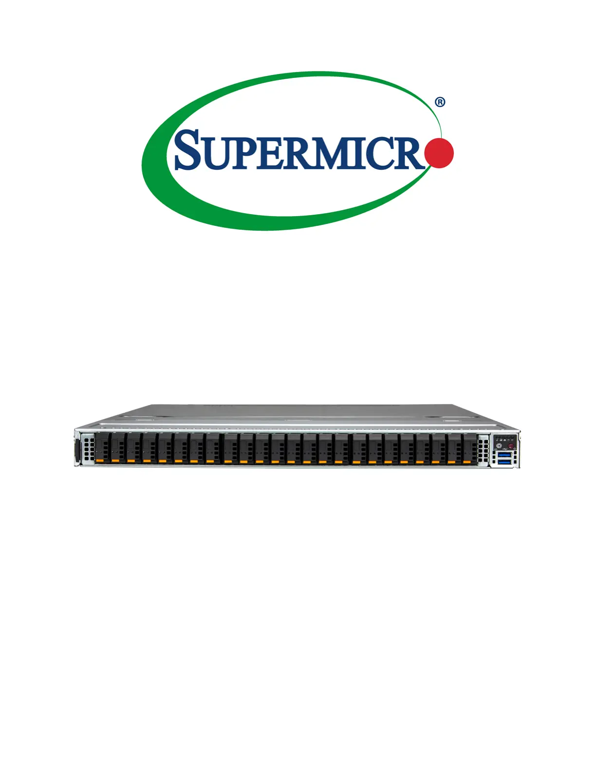
Supermicro SuperServer SSG-121E-NES24R Manual
Supermicro
Ikke kategoriseret
SuperServer SSG-121E-NES24R
Læs gratis den danske manual til Supermicro SuperServer SSG-121E-NES24R (122 sider) i kategorien Ikke kategoriseret. Denne vejledning er vurderet som hjælpsom af 12 personer og har en gennemsnitlig bedømmelse på 4.8 stjerner ud af 6.5 anmeldelser. Har du et spørgsmål om Supermicro SuperServer SSG-121E-NES24R, eller vil du spørge andre brugere om produktet?
Side 1/122

USER’S MANUAL
Revision 1.0
SuperServer®
SSG-121E-NES24R

The information in this User’s Manual has been carefully reviewed and is believed to be accurate. The vendor assumes
no responsibility for any inaccuracies that may be contained in this document, and makes no commitment to update
or to keep current the information in this manual, or to notify any person or organization of the updates. Please Note:
For the most up-to-date version of this manual, please see our website at www.supermicro.com.
Super Micro Computer, Inc. ("Supermicro") reserves the right to make changes to the product described in this manual
at any time and without notice. This product, including software and documentation, is the property of Supermicro and/
or its licensors, and is supplied only under a license. Any use or reproduction of this product is not allowed, except
as expressly permitted by the terms of said license.
IN NO EVENT WILL Super Micro Computer, Inc. BE LIABLE FOR DIRECT, INDIRECT, SPECIAL, INCIDENTAL,
SPECULATIVE OR CONSEQUENTIAL DAMAGES ARISING FROM THE USE OR INABILITY TO USE THIS PRODUCT
OR DOCUMENTATION, EVEN IF ADVISED OF THE POSSIBILITY OF SUCH DAMAGES. IN PARTICULAR, SUPER
MICRO COMPUTER, INC. SHALL NOT HAVE LIABILITY FOR ANY HARDWARE, SOFTWARE, OR DATA STORED
OR USED WITH THE PRODUCT, INCLUDING THE COSTS OF REPAIRING, REPLACING, INTEGRATING,
INSTALLING OR RECOVERING SUCH HARDWARE, SOFTWARE, OR DATA.
Any disputes arising between manufacturer and customer shall be governed by the laws of Santa Clara County in the
State of California, USA. The State of California, County of Santa Clara shall be the exclusive venue for the resolution
of any such disputes. Supermicro's total liability for all claims will not exceed the price paid for the hardware product.
FCC Statement: This equipment has been tested and found to comply with the limits for a Class A or Class B digital
device pursuant to Part 15 of the FCC Rules. These limits are designed to provide reasonable protection against
harmful interference when the equipment is operated in industrial environment for Class A device or in residential
environment for Class B device. This equipment generates, uses, and can radiate radio frequency energy and, if not
installed and used in accordance with the manufacturer’s instruction manual, may cause harmful interference with
radio communications. Operation of this equipment in a residential area is likely to cause harmful interference, in
which case you will be required to correct the interference at your own expense.
California Best Management Practices Regulations for Perchlorate Materials: This Perchlorate warning applies only
to products containing CR (Manganese Dioxide) Lithium coin cells. “Perchlorate Material-special handling may apply.
See ”.www.dtsc.ca.gov/hazardouswaste/perchlorate
WARNING: This product can expose you to chemicals including
lead, known to the State of California to cause cancer and birth
defects or other reproductive harm. For more information, go
to www.P65Warnings.ca.gov.
!
The products sold by Supermicro are not intended for and will not be used in life support systems, medical equipment,
nuclear facilities or systems, aircraft, aircraft devices, aircraft/emergency communication devices or other critical
systems whose failure to perform be reasonably expected to result in signicant injury or loss of life or catastrophic
property damage. Accordingly, Supermicro disclaims any and all liability, and should buyer use or sell such products
for use in such ultra-hazardous applications, it does so entirely at its own risk. Furthermore, buyer agrees to fully
indemnify, defend and hold Supermicro harmless for and against any and all claims, demands, actions, litigation, and
proceedings of any kind arising out of or related to such ultra-hazardous use or sale.
Manual Revision 1.0
Release Date: March 08, 2023 vc
Unless you request and receive written permission from Super Micro Computer, Inc., you may not copy any part of this
document. Information in this document is subject to change without notice. Other products and companies referred
to herein are trademarks or registered trademarks of their respective companies or mark holders.
Copyright © 2023 by Super Micro Computer, Inc.
All rights reserved.
Printed in the United States of America

4
Preface
Contents
Chapter 1 Introduction
1.1 Overview ...............................................................................................................................9
1.2 System Features ................................................................................................................10
Front View .........................................................................................................................10
Drive Carrier Indicators ..................................................................................................10
Control Panel .................................................................................................................12
Rear View ..........................................................................................................................13
Power Supply Indicator ..................................................................................................13
1.3 System Architecture ...........................................................................................................14
1.4 Motherboard Layout ...........................................................................................................16
Quick Reference Table ......................................................................................................17
Motherboard Block Diagram .............................................................................................19
Chapter 2 Server Installation
2.1 Overview .............................................................................................................................20
2.2 Unpacking the System .......................................................................................................20
2.3 Preparing for Setup ............................................................................................................20
Choosing a Setup Location ...............................................................................................20
Rack Precautions ..............................................................................................................21
Server Precautions ............................................................................................................21
Rack Mounting Considerations .........................................................................................21
Ambient Operating Temperature ....................................................................................21
Airow ............................................................................................................................22
Mechanical Loading .......................................................................................................22
Circuit Overloading ........................................................................................................22
Reliable Ground .............................................................................................................22
2.4 Installing the Rails ..............................................................................................................23
Identifying the Rails ...........................................................................................................23
Releasing the Inner Rail....................................................................................................24
Installing the Inner Rails on the Chassis ..........................................................................25
Installing the Outer Rails onto the Rack ...........................................................................26
2.5 Installing the Chassis into a Rack ......................................................................................27
Removing the Chassis from the Rack ..............................................................................28

7
Preface
No Video ...........................................................................................................................94
System Boot Failure .........................................................................................................94
Memory Errors ..................................................................................................................94
Losing the System Setup Conguration ...........................................................................94
When the System Becomes Unstable ..............................................................................94
7.4 Crash Dump Using BMC .....................................................................................................96
7.5 CMOS Clear .......................................................................................................................97
7.6 BMC Reset .........................................................................................................................97
7.7 Where to Get Replacement Components ..........................................................................98
7.8 Reporting an Issue .............................................................................................................98
Technical Support Procedures ..........................................................................................98
Returning Merchandise for Service ...................................................................................98
Vendor Support Filing System ..........................................................................................99
7.9 Feedback ............................................................................................................................99
7.10 Contacting Supermicro ....................................................................................................100
Appendix A Standardized Warning Statements for AC Systems
Appendix B System Specications

8
Contacting Supermicro
Headquarters
Address: Super Micro Computer, Inc.
980 Rock Ave.
San Jose, CA 95131 U.S.A.
Tel: +1 (408) 503-8000
Fax: +1 (408) 503-8008
Email: marketing@supermicro.com (General Information)
Sales-USA@supermicro.com (Sales Inquiries)
Government_Sales-USA@supermicro.com (Gov. Sales Inquiries)
support@supermicro.com (Technical Support)
RMA@supermicro.com (RMA Support)
Webmaster@supermicro.com (Webmaster)
Website: www.supermicro.com
Europe
Address: Super Micro Computer B.V.
Het Sterrenbeeld 28, 5215 ML
's-Hertogenbosch, The Netherlands
Tel: +31 (0) 73-6400390
Fax: +31 (0) 73-6416525
Email: Sales_Europe@supermicro.com (Sales Inquiries)
Support_Europe@supermicro.com (Technical Support)
RMA_Europe@supermicro.com (RMA Support)
Website: www.supermicro.nl
Asia-Pacic
Address: Super Micro Computer, Inc.
3F, No. 150, Jian 1st Rd.
Zhonghe Dist., New Taipei City 235
Taiwan (R.O.C)
Tel: +886-(2) 8226-3990
Fax: +886-(2) 8226-3992
Email: Sales-Asia@supermicro.com.tw (Sales Inquiries)
Support@supermicro.com.tw (Technical Support)
RMA@supermicro.com.tw (RMA Support)
Website: www.supermicro.com.tw

10
Chapter 1: Introduction
1.2 System Features
The following views of the system display the main features.
Front View
Figure 1-1. Front View
Logical Storage Drive Numbers
Item Description
0 – 23 24 hot-swap E1.S (15mm or 9.5mm) NVMe drive bays (x4 PCIe Gen5) storage system
Drive Carrier Indicators
Each drive carrier has two LED indicators: an activity indicator and a status indicator. For RAID
congurations using a controller, the meaning of the status indicator is described in the table
below. For OS RAID or non-RAID congurations, some LED indications are not supported,
such as hot spare. For VROC congurations, refer to the VROC section in this manual.
System Features: Front
Feature Description
Control Panel One control Panel (see for details)Control Panel
Pull-out Tag The pull-out service or asset tag has the BMC password details.
USB Ports Two USB 3.0 ports
0 1 2 3 4 5 6 7 8 9 10 11 12 13 14 15 16 17 18 19 20 21 22 23
Control
Panel
Pull-out Tag
USB Ports

12
Chapter 1: Introduction
Control Panel Features
Feature Description
Power button The main power switch applies or removes primary power from the power supply to the server
but maintains standby power.
Reset/UID
Button This button can also be used to . The reset button is used to reboot the systemreset the BMC
Power LED Indicates power is being supplied to the system power supply units. This
LED is illuminated when the system is operating normally.
HDD Indicates activity on the storage drives when ashing.
NIC LEDs Indicates network activity on LANs when ashing.
Power Fail LED Indicates a power supply module has failed.
Information LED Alerts operator to several states, as noted in the table below.
Information LED
Color, Status Description
Red, continuously An overheat condition has occurred.
Red, blinking at 1Hz Fan failure, check for an inoperative fan.
Red, blinking at 0.25Hz Power failure, check for a non-operational power
supply.
Blue, solid UID has been activated locally to locate the
server in a rack environment.
Blue, blinking UID has been activated using the BMC to locate
the server in a rack environment.
Control Panel
Figure 1-2. Control Panel
Information LED
NIC LED
NIC LED
HDD
Power LED
Power
Reset

13
Chapter 1: Introduction
Rear View
Figure 1-3. System: Rear View
System Features: Rear
Feature Description
Power Supplies Two redundant power supply modules, PWS1 on the right, PWS2 on the left
IPMI Port Dedicated LAN port for IPMI; for indicator details, see BMC LAN LEDs
USB Ports Two USB 3.0 ports
VGA One video port
PWS2 PWS1
VGA
Port
IPMI Port
USB
Ports
12
A1
A2
Expansion Card Chassis Slots
Item Description
1 PCIe 5.0 x16 slot
2PCIe 5.0 x16 slot
A1 AIOM1
A2 AIOM2
Power Supply Indicator
LED Color and State Power Supply Condition
O No AC power to modules
Amber, solid AC cord unplugged and in redundant mode OR power supply critical events causing
a shutdown, failure, OCP, OVP, fan fail, OTP, UVP
Amber, blinking Power supply warning events where the power supply continues to operate: high
temperature, over voltage, under voltage, etc
Green, blinking AC present, only 12vsb on (module o)
Green, solid Output on, functioning normally

14
Chapter 1: Introduction
1.3 System Architecture
This section shows the locations of the system electronic components.
Figure 1-4. Main Component Locations
Motherboard
X13DSF-A
DIMM Slots
Processors,
Heatsinks
Power Supply
Modules
Storage Backplane
BPN-E1S5-126ES2N
System Fans System Fans
M.2 Drives

17
Chapter 1: Introduction
Quick Reference Table
Jumper Description Default Setting
JBT1 CMOS Clear Open (Normal)
JRU1 UID LED/BMC Reset/System Reset Pins 1-2: UID LED/BMC Reset (Default)
Pins 2-3: System Reset
LED Description Status
LEDBMC BMC Heartbeat LED Blinking Green: BMC Normal (Active),
Solid Green: (During BMC Reset or during a Cold Reboot)
LEDPWR Power LED LED On: Onboard Power On
Connector Description
BT1 Onboard CMOS Battery
FAN1 - FAN8 4-pin Cooling Fan Headers
JFP1 Front Control Panel Header with I²C
JIPMB1 4-pin BMC External I2C Header
JL1 Chassis Intrusion Header
JNCSI1 Network Controller Sideband Interface (NC-SI) Connector for BMC shared LAN
JPW1, JPW2 8-pin Power Connectors
JPW3 4-pin Power Connector
JRK1 Intel VROC Key Header for NVMe RAID support
JSB1 Rear I/O Module Connector
JTPM1 Trusted Platform Module/Port 80 Connector
M.2-H1, M.2-H2 NVMe PCIe 3.0 p17-x4 / SATA 3.0 Hybrid M.2 Slots (Support M-Key 2280 and 22110)
MT1_1, MT2_1;
MT1_2, MT2_2
MT1_1, MT2_1: M.2-H1 Mounting Holes;
MT1_2, MT2_2: M.2-H2 Mounting Holes
P1-AIOM (J139),
P2-AIOM (J7)
Supermicro Advanced Input/Output Module (AIOM) PCIe 5.0 x16 Connectors for rear I/O
support (OCP 3.0 SFF compliant)
P1_NVME0/1 -
P1_NVME10/11 Six PCIe 5.0 x8 MCIO Connectors supported by CPU1
P2_NVME0/1 -
P2_NVME10/11 Six PCIe 5.0 x8 MCIO Connectors supported by CPU2
P1_PE1 0-15 (J1) GenZ x16 Slot (PCIe 5.0) supported by CPU1
P2_PE1 0-15 (J3) GenZ x16 Slot (PCIe 5.0) supported by CPU2
PSU1, PSU2 Power Supply Unit Connectors for system power use
SATA 0~3 (JS1) SlimSAS LP Connector with support of four Intel PCH SATA 3.0 connections (Supports
RAID 0, RAID 1, RAID 5, and RAID 10)
USB2/3 (3.0) USB 3.0 Header for front panel USB 3.0 ports

22
Chapter 2: Server Installation
Airow
Equipment should be mounted into a rack so that the amount of airow required for safe
operation is not compromised.
Mechanical Loading
Equipment should be mounted into a rack so that a hazardous condition does not arise due
to uneven mechanical loading.
Circuit Overloading
Consideration should be given to the connection of the equipment to the power supply circuitry
and the eect that any possible overloading of circuits might have on overcurrent protection
and power supply wiring. Appropriate consideration of equipment nameplate ratings should
be used when addressing this concern.
Reliable Ground
A reliable ground must be maintained at all times. To ensure this, the rack itself should be
grounded. Particular attention should be given to power supply connections other than the
direct connections to the branch circuit (i.e. the use of power strips, etc.).
To prevent bodily injury when mounting or servicing this unit in a rack, you must take
special precautions to ensure that the system remains stable. The following guidelines
are provided to ensure your safety:
• This unit should be mounted at the bottom of the rack if it is the only unit in the rack.
• When mounting this unit in a partially lled rack, load the rack from the bottom to the top
with the heaviest component at the bottom of the rack.
• If the rack is provided with stabilizing devices, install the stabilizers before mounting or
servicing the unit in the rack.
• Slide rail mounted equipment is not to be used as a shelf or a work space.
Produkt Specifikationer
Mærke: | Supermicro |
Kategori: | Ikke kategoriseret |
Model: | SuperServer SSG-121E-NES24R |
Har du brug for hjælp?
Hvis du har brug for hjælp til Supermicro SuperServer SSG-121E-NES24R stil et spørgsmål nedenfor, og andre brugere vil svare dig
Ikke kategoriseret Supermicro Manualer
22 Juli 2025
21 Juli 2025
21 Juli 2025
21 Juli 2025
21 Juli 2025
21 Juli 2025
21 Juli 2025
20 Juli 2025
20 Juli 2025
20 Juli 2025
Ikke kategoriseret Manualer
- Dragonshock
- Scosche
- Barazza
- Meradiso
- ClimeMET
- Everdure
- Tuur
- Vulcan
- President
- Thetford
- Laurastar
- CubuSynth
- Bang And Olufsen
- Cuggl
- ETiger
Nyeste Ikke kategoriseret Manualer
28 Juli 2025
28 Juli 2025
28 Juli 2025
28 Juli 2025
28 Juli 2025
28 Juli 2025
28 Juli 2025
28 Juli 2025
28 Juli 2025
28 Juli 2025