Installation and operating
1. Basic safety information
Danger of death through electric shock or fire!
Installation should only be carried out by a qualied
The device is designed for installation on DIN top hat rails (in
accordance with IEC 60715)
It complies with product standard EN 60669-2-1
Do not operate the device outside the specied technical data
The device must be installed in an enclosed switchgear cabinet
made of metal or an appropriate re-resistant material!
After proper installation, the housing component under the
cover must not be accessible!
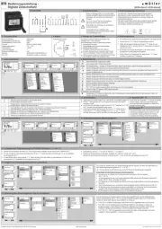
Control box TC 649 E is an annual time switch with astronomical
function, which can be controlled and updated via LAN and managed
centrally from a computer. The control box is used for lighting and
Do not use on safety devices, e.g. escape route doors, re
For an environmentally appropriate disposal, send the device back
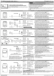
3. Installation and connection
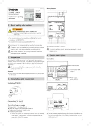
Connecting the power supply
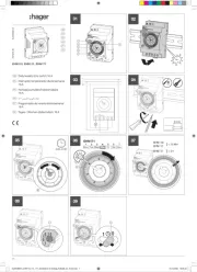
Strip cable to 8 mm (max. 9 mm)
Insert the line into the terminal and fasten it
Plug terminal into power supply socket
Connect to power supply
▻ During the start of the operating system, all LEDs are ashing.
After approx. 150 s the start process is completed and the
power LED (PWR/TLS) ashes.
LSwitch the load with a contactor.
If a load is switched directly, secure the device with a circuit
LThe performance specications can be found on the side and on
the device shoulder (see picture). After installation they are not