1User manual
FLUSH-MOUNTING WI-FI CHRONOTHERMOSTAT
Read all instructions carefully
Vemer S.p.A.
I - 32032 Feltre (BL) • Via Camp Lonc, 16
e-mail: info@vemer.it - web site: www.vemer.it
V3IS01070-011 Mod. Asso Wi-Fi
Flush-mounting Wi-Fi chronothermostat powered by mains (230V ~), suitable for
controlling heating and air conditioning systems. The Wi-Fi module allows you to
control the device remotely with your smartphone. Simply connect the device to your
home router and install the free Vemer Wi-Fi app on your smartphone, available free
of charge for iOS and Android devices. The adapters in the package allow you to
install the device with the plates of the main civil series.
Code Model Description
VE780200 Asso Wi-Fi Flush-mounting Wi-Fi chronothermostat
VE780201 Asso Wi-Fi-INT Flush-mounting Wi-Fi chronothermostat
SAFETY WARNINGS
During installation and operation of the device, it is necessary to comply with the
following instructions:
1) The device must be installed by a qualified person, in strict compliance
with the connection diagrams.
2) Do not power on or connect the device if any part of it is damaged.
3) After installation, inaccessibility to the connection terminals without appropriate
tools must be guaranteed.
4) The device must be installed and activated in compliance with current electric
systems standards.
5) Before accessing the connection terminals, verify that the leads are not live.
6) In the electrical system of the building where the chronothermostat must be
installed, a protection device from the overcurrents must be present.
7) The device performs actions of 1B type and is suitable for environments with
pollution degree 2 and overvoltage category III (EN 60730-1).
TECHNICAL FEATURES
• Power supply: 230V AC (± 10%) 50/60Hz
• Output: bistable relay with 5A / 250V AC breaking capacity
• Operating mode: summer/winter/off (with antifreeze)
• Weekly programming via app with 3 temperature levels T1, T2, T3
• Programming resolution: 1 hour
• Type of regulation: on/off or proportional
• Installation on flush-mounting box with 45mm height (occupied space: 2 modules)
• Terminal block for cables with a maximum section of 1.5mm
2
• 3-digit LED display with brightness settable from the App
• Configuration/programming key T
• Red LED: when lit it indicates that the load is active
• Green LED: configuration status
• Measurement accuracy: ± 0.5°C
• Measured temperature resolution: 0.1°C
• Temperature setting range: 2 ÷ 50°C
• Operating frequency band: 2.4GHz IEEE 802.11 b/g/n
• Maximum transmitted radiofrequency power: 18.3 dBm
• Operating temperature and humidity: 0 ÷ 50°C / 20% ÷ 90% (not cond.)
• Storage temperature: -10 ÷ 65 ° C
• Degree of protection: IP40
• Insulation: reinforced between accessible parts (front) and all other terminals
For information on the possibility of adapting the device with plates
different from those shown, contact the Technical Assistance Service.
Adapters for civil series plates for Asso Wi-Fi
Brand Series Adapter
ABB Mylos AM
AVE S44 A4
BTICINO Axolute, Axolute AIR BA
Light, Living International,
LivingLight, LivingLight AIR BL
Matix BM
GEWISS Chorus GC
VIMAR Arkè, Eikon, Eikon Evo VE
Plana VP
7EMERGENCY REGULATION
If the connection to the cloud fails (for example due to a problem with the router) it is impossible to control the device, so this regulates the temperature based on the last
programming downloaded from the cloud.
In this situation, if the temperature provided by the program does not meet your needs, you can activate the emergency mode to set a different temperature to maintain until the
connection to the cloud is re-established.
To activate the emergency regulation, proceed as follows:
① press the for about 5 seconds until appears on the displayT key SET
② the emergency temperature value flashes: pressing the T key for a long time changes the temperature value, in steps of 0.5 ° C.
With each new press, the change direction is inverted: increase-decrease-increase -...
③ when the desired value flashes on the display, wait 5 seconds without pressing the T key until appears to indicate that the device has memorized the value.MEM
When the emergency regulation is active, the measured temperature value flashes
The device automatically stops the emergency regulation as soon as the connection to the cloud is restored.
8DEVICE RESET
The reset procedure deletes all the settings made and returns the device to
the factory conditions.
The reset also deletes the configuration of the connection with the home network.
To reset, press the for about 15 seconds until the display shows T key
the word DEF.
Note. After a few seconds from the start of the pressure, the display shows
the word SET: continue to press the key without releasing it.
21.7 DEFSET
15s
MESSAGGES
During normal operation, the device displays the measured temperature.
In the initial configuration phase and in particular situations, the temperature
display is alternated with the following messages:
• CFG: device waiting for the first configuration. This situation occurs during the
initial configuration or after a device reset.
• LAN: device not yet connected to the home router. If this condition persists, check
that the password of the home wi-fi network entered in the app is correct and that
the home router is turned on.
• NET: device connected to the home router but not yet connected to the Vemer
server
• CLD: device not associated with any user (for example because it has been
disconnected or because an error has occurred in the server).
• UDP: device not connected to the NTP server for clock synchronization.
Check that the UDP123 port on the router is not blocked
• ERP: malfunction of the temperature probe
INITIAL CONFIGURATION
To configure the device proceed as follows:
① Install and start the Clima Wi-Fi app on your smartphone.
Create a personal account on the Vemer cloud (if you already have an account,
go to step 2):
ⒶTap on “Register”
ⒷEnter an email address and password and tap on “Register”.
For security reasons, it is advisable to enter a password different
from the one used to access your email
Check your email box: click on the link contained in the email receivedⒸ
to confirm the activation of the account.
② Enter the email and password of your personal Vemer account.
Tap on “New thermostat” and choose the Asso Wi-Fi model.
③ Power up the device: the green LED flashes quickly for a few seconds,
then flashes slowly for about 5 minutes (access point mode).
If the green LED does not flash, press the key T.
④ Tap on “next” and then on the name of the network “AWV...”
(the last 3 digits of the AWV network are also shown on the device
display)
Wait for the green LED to stop flashing and become steady on to indicate
that the connection between the device and the app has taken place.
⑤ In the next screen tap on the name of the home wi-fi network to which
to connect the device. Enter the password of the home wi-fi network.
⑥ Enter a name and choose an icon to help identify the Asso Wi-Fi device.
The configuration procedure has ended.
The newly configured device will appear in the list screen of the devices
associated with your account and from this moment it is possible to control
it remotely via the app.
6
3CONNECTION DIAGRAMS
L N
5A/250V~
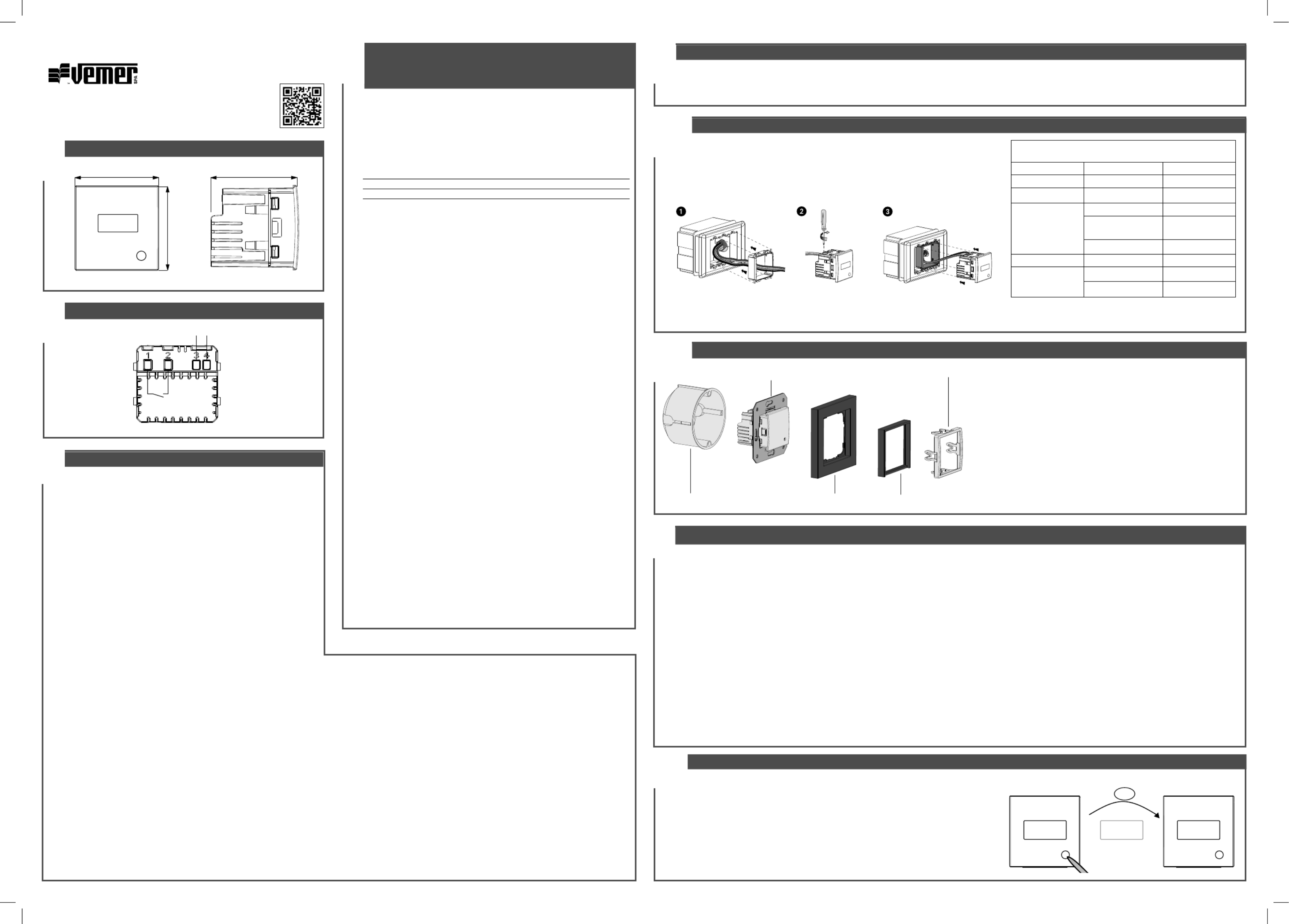
DIMENSIONS
240 42
40
4PLACEMENT
We recommend installing the device at a height of 1.5 meters from the floor, in an area that reflects as much as possible the average temperature conditions of the room.
Avoid installation near doors or windows, in niches, behind doors and curtains or in positions with excess or total lack of ventilation.
Also make sure that the distance from the router is such as to ensure stable communication.
5a ASSO WI-FI MOUNTING (code VE780200)
① Apply the adapter corresponding to the plate of the civil series to be mounted (see table)
Connect the load and the power supply (see connection diagram)②
③ Insert the device into the adapter
5b ASSO WI-FI -INT MOUNTING (code VE780200)
① Connect the load and power supply (see connection diagram)
② Fasten the device with the metal frame to the flush mounting box
③ Apply the cover plate and the 50x50mm intermediate panel
④ Finally insert the closing frame
The device can be adapted to the cover plates of Berker, Busch-Jaeger, Gira,
Jung and Merten.
The complete list of compatible cover plates is available on the website
www.vemer.it on the product page.
Flush-mounting box