Vimar 01900 Manual
Vimar
Audio tuner
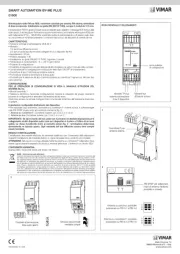
01900

| Mærke: | Vimar |
| Kategori: | Audio tuner |
| Model: | 01900 |
Har du brug for hjælp?
Hvis du har brug for hjælp til Vimar 01900 stil et spørgsmål nedenfor, og andre brugere vil svare dig
Audio tuner Vimar Manualer
29 Marts 2025
Audio tuner Manualer
- IMG Stage Line
- Technics
- Arcam
- Dual
- Meridian
- Cambridge
- Rotel
- Sirius
- Revox
- Sony
- Albrecht
- Yamaha
- Quad
- APart
- IMG Stageline
Nyeste Audio tuner Manualer

4 Januar 2026
20 September 2025
13 September 2025
11 September 2025
21 August 2025
10 August 2025
9 August 2025
6 August 2025
5 August 2025
4 August 2025