Vimar 30571.C Manual

Vimar Termostat 30571.C

Læs gratis den danske manual til Vimar 30571.C (10 sider) i kategorien Termostat. Denne vejledning er vurderet som hjælpsom af 64 personer og har en gennemsnitlig bedømmelse på 4.4 stjerner ud af 32.5 anmeldelser. Har du et spørgsmål om Vimar 30571.C, eller vil du spørge andre brugere om produktet?

Side 1/10
Viale Vicenza, 14
36063 Marostica VI - Italy
www.vimar.com
30571.x-0297 01 22012
30571.x - 02972
WELL-CONTACT PLUS
Termostato elettronico a rotella per controllo della temperatura ambiente
(riscaldamento e condizionamento), domotica standard KNX, dispositivo di
controllo della temperatura di classe I (contributo 1%) in modalità ON/OFF,
di classe IV (contributo 2%) in modalità PI, interfacciabile con attuatore con
uscite analogiche proporzionali KNX per realizzare un termostato d’ambiente
modulante di classe V (contributo 3%), 1 ingresso per sensore elettronico di
temperatura 20432, 19432 o 14432 o sensore di temperatura filare 02965.1,
1 ingresso digitale programmabile, retroilluminazione a led bianca, grigio - 2
moduli. Da completare con placche Linea, Eikon, Arké, Plana. Per Idea instal-
labile con supporto dedicato 16723.
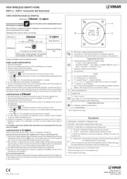
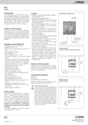
Il termostato è provvisto di rotella frontale per l’impostazione del setpoint (da 4°C a 40°C) e di
un display centrale retroilluminato a led bianchi che visualizza la temperatura misurata mostran-
do il setpoint solo quando si agisce sulla rotella. La ghiera intorno al display, retroilluminata in
RGB, visualizza tutti gli stati del termostato. Il dispositivo è provvisto di 4 tasti frontali utilizzabili
per le impostazioni. La configurazione del termostato, dell’indirizzo fisico, dei parametri e del
suo funzionamento avviene mediante il software ETS.
CARATTERISTICHE.
Tensione di alimentazione BUS: 29 V
Assorbimento dal BUS: 17,5 mA
Morsetti:
- 2 per bus KNX
- 2 per sonda si temperatura esterna (art. 02965.1 e 20432-19432-14432)
Lunghezza massima del cavo di collegamento del sensore esterno: 60 m.
- 2 per ingresso digitale privo di potenziale (SELV)
Lunghezza massima del cavo di collegamento su ingresso contatto pultito: 30 m.
Per gli ingressi utilizzare un cavo twistato con sezione minima di 0.5 mm
2 (art. 01840).
4 tasti frontali per comando e configurazione/reset.
LED RGB per segnalazione stato di configurazione (lampeggiante blu) e lo stato dell’uscita
(colore configurabile).
Precisione misura temperatura:
- sensore integrato: range di misura da 0 a 40°, ±0.5 °C tra 15 °C e 30 °C, ±0.8 °C agli
estremi;
- sensore esterno ausiliare: come sensore integrato. Oltre alla temperatura di funzionamento
del dispositivo l’errore del sensore esterno ausiliario aumenta fino ad un max di 2.5°C @
80°C.
Differenziale termico: regolabile tra 0.1°C e 1°C
Gestione Impianti con 2 e 4 tubi.
Riscaldamento, condizionamento con gestione della zona neutra (solo con 4 tubi).
Pilotaggio tramite apposito attuatore di valvole caldo/freddo di tipo On/Off o di tipo propor-
zionale (0-10 V, 4-20 mA).
Gestione fancoil (3 velocità/proporzionali, valvole on/off).
Algoritmo di regolazione ON/OFF o PID selezionabile:
- l’algoritmo ON/OFF è il controllo nel quale, al superamento della temperatura impostata
aumentata di un valore di soglia (viceversa per il condizionamento), il riscaldamento viene
spento per poi riaccendersi quando la temperatura ambiente scende al di sotto della
temperatura impostata.
- il PID è un algoritmo evoluto in grado di mantenere più stabile la temperatura dell’ambiente
e agisce accendendo e spegnendo opportunamente l’impianto in modo da risultare come
un graduale aumento o calo della potenza termica (o refrigerante) dell’impianto stesso;
ideale negli impianti a pavimento, l’algoritmo necessita di essere opportunamente calibrato
in base al tipo di ambiente e di impianto.
Funzione boost: comando di un attuatore ausiliario per velocizzare il riscaldamento o il con-
dizionamento dell’ambiente.
Funzione Mezza stagione: disponibile da supervisore solo per impianti configurati a 4 tubi,
quando è attiva viene comandata l’uscita secondaria con i propri parametri.
Ingresso per sensore esterno (art. 02965.1-20432-19432-14432) le cui funzioni sono le
seguenti:
- Sostituzione del sensore interno.
- Media con quello interno.
- Limitazione temperatura massetto.
- Sola visualizzazione su display.
Funzione di gestione finestra aperta con gestione del ritardo in accensione e spegnimento.
Dispositivo gestibile da remoto.
Dispositivo interfacciabile in modo nativo con sistemi di terze parti (sistemi KNX).
Possibilità di utilizzare un offset per correggere la lettura della temperatura misurata in accor-
do con eventuale termometro campione in modo da compensare errori dovuti ad installazioni
particolari (muro a nord, vicinanza a tubi acqua calda/fredda, ecc.).
Temperatura di funzionamento: 0 °C +40 °C (uso interno).
Classificazione ErP (Reg. UE 811/2013): - ON/OFF: classe I, contributo 1%. - PID: classe IV,
contributo 2%.
Configurabile tramite il software ETS.
FUNZIONAMENTO.
Attraverso i tasti frontali, il display, la rotella e la ghiera che la delimita è possibile personalizzare
e visualizzare le modalità di funzionamento ON/OFF del termostato, lo stato dell’impianto (in
funzione o no) nonché la modalità stagionale (raffrescamento, riscaldamento).
RAEE - Informazione agli utilizzatori
Il simbolo del cassonetto barrato riportato sullapparecchiatura o sulla sua confezione indica che il prodotto alla fine della propria vita utile
deve essere raccolto separatamente dagli altri rifiuti. Lutente dovrà, pertanto, conferire l’apparecchiatura giunta a fine vita agli idonei centri
comunali di raccolta differenziata dei rifiuti elettrotecnici ed elettronici. In alternativa alla gestione autonoma, è possibile consegnare gra-
tuitamente l’apparecchiatura che si desidera smaltire al distributore, al momento dell’acquisto di una nuova apparecchiatura di tipo equi-
valente. Presso i distributori di prodotti elettronici con supercie di vendita di almeno 400 m
2 è inoltre possibile consegnare gratuitamente,
senza obbligo di acquisto, i prodotti elettronici da smaltire con dimensioni inferiori a 25 cm. Ladeguata raccolta differenziata per l’avvio
successivo dell’apparecchiatura dismessa al riciclaggio, al trattamento e allo smaltimento ambientalmente compatibile contribuisce ad evi-
tare possibili effetti negativi sull’ambiente e sulla salute e favorisce il reimpiego e/o riciclo dei materiali di cui è composta l’apparecchiatura.
CONFIGURAZIONE.
Per tutti i dettagli relativi agli oggetti di comunicazione ETS, ai parametri e alla configu-
razione del dispositivo, si consulti il manuale Welll-contact Plus scaricabile dalla sezione
“Download -> Software -> Well-contact Plus” del sito www.vimar.com.
Lutente, mediante i tasti frontali, pot modificare il set point di temperatura e la velocità del fan-
coil; la modifica di questi parametri forza il termostato in funzionamento manuale.
REGOLE DI INSTALLAZIONE.
L’installazione e la configurazione deve essere effettuata da personale qualificato con l’os-
servanza delle disposizioni regolanti l’installazione del materiale elettrico in vigore nel paese
dove i prodotti sono installati.
• L’apparecchio deve essere installato in scatole da incasso o da parete con i relativi supporti e
placche, a un’altezza di 1,5 m dal piano di calpestio, in una posizione idonea alla corretta rile-
vazione della temperatura ambiente, evitando l’installazione in nicchie, dietro porte e tende,
zone influenzate da fonti di calore o soggette al flusso di sorgenti a ventilazione forzata di
riscaldamento/raffrescamento o influenzate da fattori atmosferici. In particolare si deve evitare
l’installazione su pareti perimetrali o in associazione ad apparecchi che generano calore (es.
regolatori o lampade).
CONFORMITÀ NORMATIVA.
Direttiva EMC. Direttiva RoHS. Norme EN IEC 60669-2-1, EN50491-2, EN IEC 63044, EN
IEC 63000.
Regolamento dispositivi di controllo della temperatura (UE) 811/2013.
Regolamento REACh (UE) n. 1907/2006 art.33. Il prodotto potrebbe contenere tracce di
piombo.
Electronic dial thermostat for room temperature control (heating and air
conditioning), KNX standard home automation system, class I temperature
control device (contribution 1%) in ON/OFF mode, class IV (contribution 2%)
in PID mode, can be interfaced with actuator with KNX proportional analogue
outputs to implement a class V modulating room thermostat (contribution
3%), 1 input for electronic temperature sensor 20432, 19432 or 14432 or
wired temperature sensor 02965.1, 1 programmable digital input, white/grey
LED backlighting - 2 modules. To be completed with Linea, Eikon, Arké,
Plana cover plates. For Idea, can be installed using the dedicated mounting
frame 16723.
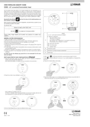
The thermostat is fitted with a front dial to adjust the setpoint (between 4°C and 40°C) and a
central white LED backlit display to show the measured temperature, and show the setpoint
only when the dial is being used. The circular ring around the display, with RGB backlighting,
displays all the thermostat statuses. The device is fitted with 4 front buttons to be used for
setting. The thermostat, physical address, parameters and its operation, etc. are configured
via the ETS software.
CHARACTERISTICS.
BUS supply voltage: 29 V
Absorption from the BUS: 17.5 mA
• Terminals:
- 2 for KNX bus
- 2 for external temperature probe (art. 02965.1 and 20432-19432-14432)
Maximum length of the external sensor connection cable: 60 m.
- 2 for voltage-free digital input (SELV)
Maximum length of the connection cable on the voltage-free contact input: 30 m.
For the inputs, use a twisted cable with a minimum cross-section of 0.5 mm
2 (art. 01840).
4 front buttons for control and configuration/reset.
RGB LED for configuration status (flashing blue) and output status (configurable colour)
signalling.
Temperature measurement precision:
- built-in sensor: measurement range from 0 to 40°, ±0.5 °C between 15 °C and 30 °C, ±0.8
°C at the extremes;
- auxiliary external sensor: like the built-in sensor. Beyond the operating temperature of the
device, the error of the auxiliary external sensor increases up to max 2.5°C @ 80°C.
Hysteresis: adjustable from 0.1°C to 1°C
Management of 2- and 4-pipe systems.
Heating, air conditioning with management of the neutral zone (only with 4 pipes).
Operation via a dedicated ON/OFF or proportional hot/cold valve actuator (0-10 V, 4-20 mA).
Fan coil management (3 speeds/proportional, ON/OFF valves).
Selectable PID or ON/OFF control algorithm:
- the ON/OFF algorithm is the control which, on exceeding the set temperature increased by
the threshold value (vice versa for air conditioning), the heating is switched off to then be
turned back on when the room temperature drops below the set temperature.
Viale Vicenza, 14
36063 Marostica VI - Italy
www.vimar.com
30571.x-0297 01 22012
30571.x - 02972
WELL-CONTACT PLUS
- PID is a sophisticated algorithm capable of keeping the temperature in the setting more
stable and it works by switching the system on and off so as to be like a gradual increase
or decrease in the system’s thermal (or refrigerating) power; ideal for use in floor heating
systems, the algorithm needs to be properly calibrated according to the type of environ-
ment and system.
Boost function: control of an auxiliary actuator to speed up the heating or air conditioning of
the environment.
Mild season function: available from the supervisor only for systems configured with 4 pipes;
when active, the secondary output is controlled with its own parameters.
Input for external sensor (art. 02965.1-20432-19432-14432) with the following functions:
- Replacement of the internal sensor.
- Average with the internal one.
- Screed temperature limitation.
- Display on display only.
Open window management function with delayed power on and off management.
Remote manageable device.
Device can be interfaced natively with third-party systems (KNX systems).
Possibility of using an offset to correct the reading of the temperature measured according to
a possible sample thermometer in order to compensate for errors due to special installations
(North-facing wall, proximity to hot/cold water pipes, etc.).
Operating temperature: 0 °C +40°C (indoor use).
ErP classification (EU Reg. 811/2013): - ON/OFF: class I, contribution 1%. - PID: class IV,
contribution 2%.
Configurable via ETS software.
OPERATION.
The front buttons, display, dial and circular ring around the display can be used to customise
and display the ON/OFF operating modes of the thermostat, the state of the system (operating
or not) and the seasonal mode (air conditioning, heating).
CONFIGURATION.
For all the details relating to the ETS communication objects and to the device config-
uration, please consult the Well-contact Plus manual available for downloading under
“Download -> Software -> Well-contact Plus” on the www.vimar.com website.
Using the front keys, the user can modify the temperature set point and the speed of the fan coil;
modifying these parameters forces the thermostat into manual operation.
INSTALLATION RULES.
Installation and configuration must be carried out by qualified persons in compliance with the
current regulations regarding the installation of electrical equipment in the country where the
products are installed.
The device must be installed in a flush mounting box or surface mounting box with the related
mounting frames and cover plates, at a height of 1.5 m above floor level, in a suitable position
for the correct detection of the room temperature, avoiding installation in recesses, behind
doors and curtains, areas affected by heat sources or subject to the flow of forced heating/
cooling ventilation sources or affected by atmospheric factors. Avoid in particular installation
on perimeter walls or in association with devices which generate heat (e.g. dimmers or
lamps).
REGULATORY COMPLIANCE.
EMC directive. RoHS directive. Standards EN IEC 60669-2-1, EN50491-2, EN IEC 63044,
EN IEC 63000.
Temperature control device regulation (EU) no. 811/2013.
REACH (EU) Regulation no. 1907/2006 Art.33. The product may contain traces of lead.
WEEE - User information
The crossed bin symbol on the appliance or on its packaging indicates that the product at the end of its life must be collected separately
from other waste. The user must therefore hand the equipment at the end of its life cycle over to the appropriate municipal centres for the
differentiated collection of electrical and electronic waste. As an alternative to independent management, you can deliver the equipment
you want to dispose of free of charge to the distributor when purchasing a new appliance of an equivalent type. You can also deliver
electronic products to be disposed of that are smaller than 25 cm for free, with no obligation to purchase, to electronics distributors with a
sales area of at least 400 m
2. Proper sorted waste collection for subsequent recycling, processing and environmentally conscious disposal
of the old equipment helps to prevent any possible negative impact on the environment and human health while promoting the practice of
reusing and/or recycling materials used in manufacture.
Thermostat électronique à molette pour le contrôle de la température
ambiante (chauffage et climatisation), domotique standard KNX, dispositif
de contrôle de la température appartenant à la classe I (contribution 1%) en
modalité ON/OFF, à la classe IV (contribution 2%) en modalité PI, interfaçable
avec actuateur à sorties analogiques proportionnelles KNX pour réaliser un
thermostat d'ambiance modu classe V (contribution 3%), 1 entrée pour
capteur électronique de température 20432, 19432 ou 14432 ou capteur de
température filaire 02965.1, 1 entrée numérique programmable, rétroéclairage
à led blanche - 2 modules. À compléter avec les platines Linea, Eikon, Arké,
Plana. Pour Idea à installer sur support dédié 16723.
Le thermostat présente une molette à l’avant pour le réglage du point de consigne (de 4 °C à
40 °C) et un écran central rétroéclairé à leds blanches qui affiche la température mesurée en
montrant le point de consigne uniquement lorsque l’on tourne la molette. La couronne circulaire
autour de l’écran, rétroéclairée en RGB, affiche tous les états du thermostat. Le dispositif pré-
sente 4 touches frontales utilisables pour les réglages. Le thermostat, l'adresse physique et les
paramètres pour son fonctionnement doivent être configurés avec le logiciel ETS.
CARACTÉRISTIQUES
Tension d'alimentation BUS : 29 V
Absorption du BUS : 17,5 mA
Bornes :
- 2 pour bus KNX
- 2 pour sonde de température extérieure (art. 02965.1 et 20432-19432-14432)
Longueur maximale du ble de connexion du capteur extérieur : 60 m.
- 2 pour entrée numérique sans potentiel (SELV)
Longueur maximale du ble de connexion sur entrée contact sec : 30 m.
Pour les entrées, utiliser un câble torsaavec section minimum de 0,5 mm
2 (art. 01840).
4 touches frontales de commande et configuration/réinitialisation.
Leds RGB signalant l’état de configuration (clignotement bleu) et l’état de la sortie (couleur
configurable).
Précision mesure température :
- capteur intégré : plage de mesure de 0 à 40°, ±0,5 °C entre 15 °C et 30 °C, ±0,8 °C aux
extrémités ;
- capteur extérieur auxiliaire : comme pour le capteur intégré. Outre la température de
fonctionnement du dispositif, l’erreur du capteur extérieur auxiliaire augmente jusqu’à un
maximum de 2,5 °C @ 80 °C.
Différentiel thermique : glable entre 0,1 °C et 1 °C.
Gestion des installations à 2 et 4 tubes.
Chauffage, climatisation avec gestion de la zone neutre (uniquement avec 4 tubes).
Pilotage par actuateur de vannes chaud/froid de type On/Off ou de type proportionnel (0-10
V, 4-20 mA).
Gestion ventilo-convecteur (3 vitesses/proportionnelle, vannes on/off).
Algorithme de réglage ON/OFF ou PID sélectionnable :
- l’algorithme ON/OFF correspond au contrôle selon lequel, en cas de dépassement de
la température définie à laquelle s'ajoute la valeur de seuil (et inversement pour la clima-
tisation), le chauffage s'éteint et se rallume dès que la température ambiante descend
au-dessous de la valeur définie.
- le PID est un algorithme évolué en mesure de stabiliser la température ambiante et il
intervient en allumant et éteignant l’installation de sorte à assurer une augmentation ou
une baisse graduelle de la puissance thermique (ou de climatisation) de l’installation ; idéal
pour les installations au sol, l’algorithme doit être calibré en fonction du milieu environnant
et du type d’installation.
Fonction boost : commande d’un actuateur auxiliaire pour accélérer le chauffage ou la clima-
tisation dans la pièce/appartement.
Fonction mi-saison : disponible via superviseur exclusivement sur les installations à 4 tubes;
lorsqu’elle est activée, elle commande la sortie secondaire avec ses propres paramètres.
Entrée pour capteur extérieur (art. 02965.1-20432-19432-14432) dont les fonctions sont les
suivantes :
- Remplacement du capteur intérieur.
- Moyenne avec le capteur intérieur.
- Limitation de température chape.
- Affichage sur écran uniquement.
Fonction de gestion fenêtre ouverte avec gestion du retard à l’allumage et à l’extinction.
Dispositif pouvant être commandé à distance.
Dispositif interfaçable nativement avec les systèmes de tiers (systèmes KNX).
Possibilité d’utiliser un écart pour corriger la lecture de la température mesurée en accord
avec un éventuel thermomètre échantillon de sorte à compenser les erreurs dues aux instal-
lations spéciales (mur exposé nord, proximité de tubes hydrauliques chauds ou froids, etc.).
Température de fonctionnement : 0 °C +40 °C (usage intérieur).
Classement ErP (Règl. UE 811-2013) : - ON/OFF : classe I, contribution 1%. - PID : classe
IV, contribution 2%.
Configurable par logiciel ETS.
FONCTIONNEMENT
Les touches frontales, l’écran, la molette et la couronne circulaire qui la délimite permettent
de personnaliser et d’afficher les modes de fonctionnement ON/OFF du thermostat, l’état de
l’installation (en service ou non) ainsi que la modalité saison (climatisation, chauffage).
CONFIGURATION.
Pour tous les détails correspondant aux objets de communication ETS, aux paramètres
et à la configuration du dispositif, consulter le manuel Well-contact Plus à télécharger à
la section « Téléchargement -> Logiciel -> Well-contact Plus » sur le site www.vimar.com.
Lutilisateur pourra utiliser les touches frontales pour modifier le point de consigne température
et la vitesse du ventilo-convecteur ; en modifiant ces paramètres, il force le thermostat en fonc-
tionnement manuel.
CONSIGNES D'INSTALLATION
Le circuit et la configuration doivent être réalisés par des techniciens qualifiés, conformément
aux dispositions qui régissent l'installation du matériel électrique en vigueur dans le pays
concerné.
L’appareil doit être installé dans des boîtes d’encastrement ou en saillie, avec les supports
et les plaques correspondants, à 1,5 m du sol, dans une position permettant une mesure
correcte de la température ambiante : éviter les niches, l'arrière des portes et des rideaux,
les zones exposées aux sources de chaleur ou sujettes au flux de sources de chaleur/clima-
tisation à ventilation forcée ou influencées par des facteurs atmosphériques. Éviter surtout
de l’installer sur les cloisons périmétrales ou en combinaison avec des appareils générant de


Produkt Specifikationer

Mærke: Vimar
Kategori: Termostat
Model: 30571.C

Har du brug for hjælp?

Hvis du har brug for hjælp til Vimar 30571.C stil et spørgsmål nedenfor, og andre brugere vil svare dig


Termostat Vimar Manualer

Vimar

Vimar 02973 Manual

25 Juli 2025
Vimar

Vimar 19440.M Manual

24 Juli 2025
Vimar

Vimar 01910.14 Manual

24 Juli 2025
Vimar

Vimar 02952.BN Manual

24 Juli 2025
Vimar

Vimar 02970 Manual

24 Juli 2025
Vimar

Vimar 14440.SL Manual

24 Juli 2025
Vimar

Vimar 14446 Manual

24 Juli 2025
Vimar

Vimar 02971.M Manual

24 Juli 2025
Vimar

Vimar 02973.N Manual

24 Juli 2025

Termostat Manualer

Nyeste Termostat Manualer