IR Receivers
1
172-94
XTRA LINK
®
2
REMOTE CONTROL EXTENSION SYSTEM
INSTALLATION INSTRUCTIONS
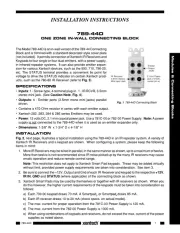
The Xtra Link 2 system provides full remote control operation of a satellite receiver, cable box or VCR from
a second room by sharing the coaxial cable connecting your video equipment to this second room’s TV.
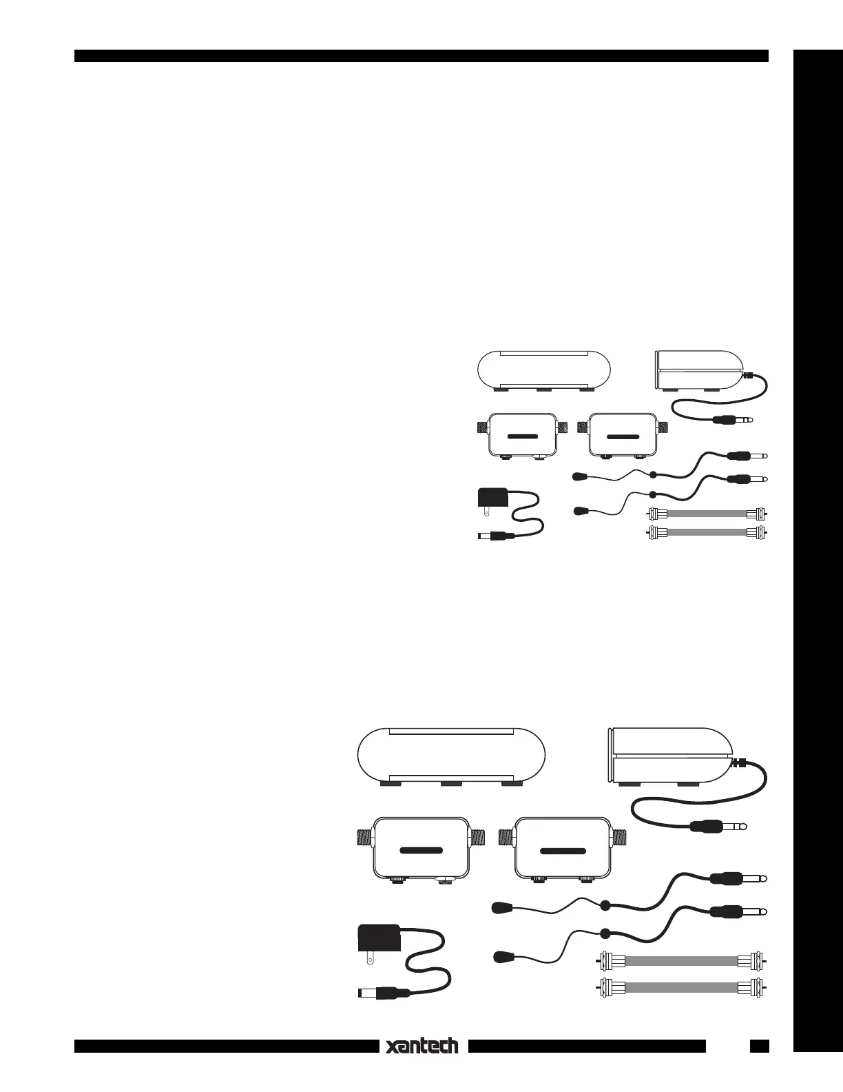
The 172-94 Xtra Link 2 consists of the following supplied parts (Fig.1):
1. One 291-00 IR Receiver. It is placed at the remote room location to receive IR signals from the
handheld remote controller.
2. One INJ94 Injector. This unit, located in the Remote
Room, injects the remote control signal into the room-
to-room coaxial cable (along with the TV signal) and
passes it to the CPL94B Coupler in the Main room. It
also provides quick connection of the 291-00 IR Re-
ceiver and 781C-00 Power Supply cables.
3. One CPL94B Coupler. Located in the Main Room,
this Coupler extracts the remote control signal from
the coaxial cable and passes it to the emitters that
control your IR remote controlled audio/video source
components. Two emitter jacks are provided for con-
trol of up to four components.
4. One 282M high output emitter and one 283M Blink-
IR
TM
emitter. These permit acontrol of two IR remote
controlled components. The visible output of the 283M allows it to also be used for troubleshooting.
5. Two short coaxial cables. One connects the TV signal source to the CPL94B Coupler in the Main
Room. The other connects the INJ94 Injector to the TV in the Remote Room.
6. A 781C-00 Power supply. This plugs into an unswitched 120V AC outlet to provide power to the 291-
00 IR Receiver.
CONNECTIONS:
The Xtra Link system uses the coaxial
cable that carries the TV RF signal from
the source equipment in the main room
to the remote room, to send the IR
control signals back to the source equip-
ment. The coaxial cable may be up to
one mile in length.
If you already have a coaxial cable con-
necting your video equipment with a re-
mote room, your current hookup should
be similar to Fig. 2. If it isn't, run a single
length of RG59 or preferably RG6 cable
from the Main Room to the Remote Room.
NOTE: If RF amplifier(s) are used any-
where in the line of coaxial cable be-
tween the CPL94B Coupler and the INJ94
282M
Mouse Emitter
Coax Jumper Cables
283M
Blink-IR™
Mouse Emitter
INJ94 Injector
+12 V
IR
RCVR
TV
INPUT
INJ94 INJECTOR
CPL94B Coupler
EMITTER
REMOTE TV
SAT/VCR
CPL94B COUPLER
EMITTER
291-00 IR Receiver
Front View
291-00 IR Receiver
Side View
781C-00
Power Supply
Fig. 1 172-94 Xtra Link 2 System Parts
282M
Mouse Emitter
Coax Jumper Cables
283M
Blink-IR™
Mouse Emitter
INJ94 Injector
+12 V
IR
RCVR
TV
INPUT
INJ94 INJECTOR
CPL94B Coupler
EMITTER
REMOTE TV
SAT/VCR
CPL94B COUPLER
EMITTER
291-00 IR Receiver
Front View
291-00 IR Receiver
Side View
781C-00
Power Supply
Fig. 2 Basic System Without Xtra Link