AMX NCITE-813A Manual

AMX Ikke kategoriseret NCITE-813A

Læs gratis den danske manual til AMX NCITE-813A (141 sider) i kategorien Ikke kategoriseret. Denne vejledning er vurderet som hjælpsom af 18 personer og har en gennemsnitlig bedømmelse på 4.8 stjerner ud af 9.5 anmeldelser. Har du et spørgsmål om AMX NCITE-813A, eller vil du spørge andre brugere om produktet?

Side 1/141
INSTRUCTION MANUAL
INCITE DIGITAL VIDEO
PRESENTATION SYSTEMS
NCITE-813
NCITE-813A
NCITE-813AC
To avoid ESD (Electrostatic Discharge) damage to sensitive components, make sure you are properly grounded before touching any internal materials.
When working with any equipment manufactured with electronic devices, proper ESD grounding procedures must be followed to make sure people, products, and tools are
as free of static charges as possible. Grounding straps, conductive smocks, and conductive work mats are specically designed for this purpose. These items should not be
manufactured locally, since they are generally composed of highly resistive conductive materials to safely drain static discharges, without increasing an electrocution risk
in the event of an accident.
Anyone performing eld maintenance on AMX equipment should use an appropriate ESD eld service kit complete with at least a dissipative work mat with a ground cord
and a UL listed adjustable wrist strap with another ground cord.
IMPORTANT SAFETY INSTRUCTIONS
1. READ these instructions.
2. KEEP these instructions.
3. HEED all warnings.
4. FOLLOW all instructions.
5. DO NOT use this apparatus near water.
6. CLEAN ONLY with dry cloth.
7. DO NOT block any ventilation openings. Install in accordance with the manufacturer’s instructions.
8. DO NOT install near any heat sources such as radiators, heat registers, stoves, or other apparatus (including ampliers) that produce heat.
9. DO NOT defeat the safety purpose of the polarized or grounding type plug. A polarized plug has two blades with one wider than the other. A grounding
type plug has two blades and a third grounding prong. The wider blade or the third prong are provided for your safety. If the provided plug does not t
into your outlet, consult an electrician for replacement of the obsolete outlet.
10. PROTECT the power cord from being walked on or pinched, particularly at plugs, convenience receptacles, and the point where they exit from the
apparatus.
11. ONLY USE attachments/accessories specied by the manufacturer.
12. USE ONLY with a cart, stand, tripod, bracket, or table specied by the manufacturer, or sold with the apparatus. When a cart is used, use caution when
moving the cart/apparatus combination to avoid injury from tip-over.
13. UNPLUG this apparatus during lightning storms or when unused for long periods of time.
14. REFER all servicing to qualied service personnel. Servicing is required when the apparatus has been damaged in any way, such as power-supply cord
or plug is damaged, liquid has been spilled or objects have fallen into the apparatus, the apparatus has been exposed to rain or moisture, does not
operate normally, or has been dropped.
15. DO NOT expose this apparatus to dripping or splashing and ensure that no objects lled with liquids, such as vases, are placed on the apparatus.
16. To completely disconnect this apparatus from the AC Mains, disconnect the power supply cord plug from the AC receptacle.
17. Where the mains plug or an appliance coupler is used as the disconnect device, the disconnect device shall remain readily operable.
18. DO NOT overload wall outlets or extension cords beyond their rated capacity as this can cause electric shock or re.
The exclamation point, within an equilateral triangle, is intended to alert the user to the presence of important operating and maintenance (servicing)
instructions in the literature accompanying the product.
The lightning ash with arrowhead symbol within an equilateral triangle is intended to alert the user to the presence of uninsulated “dangerous volt-
age” within the product’s enclosure that may be of sucient magnitude to constitute a risk of electrical shock to persons.
ESD Warning: The icon to the left indicates text regarding potential danger associated with the discharge of static electricity from an outside source
(such as human hands) into an integrated circuit, often resulting in damage to the circuit.
WARNING: To reduce the risk of re or electrical shock, do not expose this apparatus to rain or moisture.
WARNING: No naked ame sources - such as candles - should be placed on the product.
WARNING: Equipment shall be connected to a MAINS socket outlet with a protective earthing connection.
COPYRIGHT NOTICE
AMX© 2015, all rights reserved. No part of this publication may be reproduced, stored in a retrieval system, or transmitted, in any form or by any
means, electronic, mechanical, photocopying, recording, or otherwise, without the prior written permission of AMX. Copyright protection claimed extends to AMX hardware
and software and includes all forms and matters copyrightable material and information now allowed by statutory or judicial law or herein after granted, including without
limitation, material generated from the software programs which are displayed on the screen such as icons, screen display looks, etc. Reproduction or disassembly of em-
bodied computer programs or algorithms is expressly prohibited.
LIABILITY NOTICE
No patent liability is assumed with respect to the use of information contained herein. While every precaution has been taken in the preparation of this publication, AMX
assumes no responsibility for error or omissions. No liability is assumed for damages resulting from the use of the information contained herein. Further, this publication
and features described herein are subject to change without notice.
AMX WARRANTY AND RETURN POLICY
The AMX Warranty and Return Policy and related documents can be viewed/downloaded at www.amx.com.
ESD WARNING
C A U T I O N
RISK OF ELECTRIC SHOCK
DO NOT OPEN
WARNING Do Not Open! Risk of Electrical Shock. Voltages in this equipment are hazardous to life. No user-serviceable :
parts inside. Refer all servicing to qualied service personnel.
Place the equipment near a main power supply outlet and make sure that you can easily access the power breaker switch.
3
WARNING: This product is intended to be operated ONLY from the voltages listed on the back panel or the recommended, or included, power supply of the
product. Operation from other voltages other than those indicated may cause irreversible damage to the product and void the products warranty. The use of
AC Plug Adapters is cautioned because it can allow the product to be plugged into voltages in which the product was not designed to operate. If the product is
equipped with a detachable power cord, use only the type provided, or specied, by the manufacturer or your local distributor.
BATTERY INSTRUCTIONS:
THIS PRODUCT CONTAINS A LITHIUM PACK OR COIN/BUTTON CELL BATTERY. IF MISUSED OR ABUSED THIS CAN RESULT IN:
Smoke or gas hazard
Heat hazard
Fire hazard
Explosion hazard
WARNING: Do not place batteries in mouth or ingest. Chemical burn hazard. Keep new and used batteries out of reach of children and
pets. If swallowed, it can cause severe internal burns in just 2 hours and can lead to death.
If you think batteries might have been swallowed or placed inside any part of the body, seek immediate medical attention.
WARNING: If battery compartment does not close securely, stop using the product and keep it away from children and pets.
WARNING: Do not handle leaking or damaged Lithium batteries.
WARNING: Risk of leakage. Only use the specied type of batteries. Never mix new and used batteries.
Observe correct polarity. Remove batteries from products that are not in use for extended periods of time. Store batteries in a dry place.
WARNING: Batteries (battery pack or batteries installed) shall not be exposed to excessive heat such as sunshine, re or the like.
WARNING: Danger of explosion if battery is incorrectly replaced. Replace only with the same or equivalent type.
Dispose of used batteries according to the instructions.
WARNING: Do not recharge non-rechargeable batteries.
WARNING: Avoid exposure to extreme heat or cold.
Please dispose of any used batteries properly, following any local regulations. Do not incinerate.
WARNING: Disposal of a battery into re or a hot oven, or mechanically crushing or cutting of a battery, can result in an explosion.
RACK MOUNTING:
A) Elevated Operating Ambient - If installed in a closed or multi-unit rack assembly, the operating ambient temperature of the rack environment may
be greater than room ambient. Therefore, consideration should be given to installing the equipment in an environment compatible with the maximum
ambient temperature (Tma) specied by the manufacturer.
B) Reduced Air Flow - Installation of the equipment in a rack should be such that the amount of air ow required for safe operation of the equipment is
not compromised.
C) Mechanical Loading - Mounting of the equipment in the rack should be such that a hazardous condition is not achieved due to uneven mechanical
loading.
D) Circuit Overloading - Consideration should be given to the connection of the equipment to the supply circuit and the eect that overloading of the
circuits might have on overcurrent protection and supply wiring. Appropriate consideration of equipment nameplate ratings should be used when
addressing this concern.
E) Reliable Earthing - Reliable earthing of rack-mounted equipment should be maintained. Particular attention should be given to supply connections
other than direct connections to the branch circuit (e.g. use of power strips).
FCC AND CANADA EMC COMPLIANCE INFORMATION:
This device complies with part 15 of the FCC Rules. Operation is subject to the following two conditions:
(1) This device may not cause harmful interference, and (2) this device must accept any interference received,
including interference that may cause undesired operation.
NOTE: This equipment has been tested and found to comply with the limits for a Class A digital device, pursuant to part 15 of the FCC Rules. These limits
are designed to provide reasonable protection against harmful interference when the equipment is operated in a commercial environment. This equipment
generates, uses, and can radiate radio frequency energy, and if it is not installed and used in accordance with the instruction manual, it may cause harmful
interference to radio communications. Operation of this equipment in a residential area is likely to cause harmful interference, in which case the user will be
required to correct the interference at his own expense.
WARNING: This product must not be used in residential areas.
CAUTION: Changes or modications not expressly approved by the manufacturer could void the user’s authority to operate this device.
WARNING: This equipment is compliant with Class A of CISPR 32. In a residential environment this equipment may cause radio interference.
NOTE: For interference purposes, the residential and domestic environments are dened as an environment within 10meters of radio or broadcast
receiving equipment or home use. CAN ICES-3 (A)/NMB-3(A)
此为 A 级产品。在生活环境中,该产品可能会造成无线电干扰。在这种情况下,可能需要用户对干扰采取切实可行的措施
Instruction Manual - Incite Digital Video Presentation Systems
WEEE NOTICE:
This appliance is labeled in accordance with European Directive 2012/19/EU concerning waste of electrical and electronic equipment (WEEE).
This label indicates that this product should not be disposed of with household waste. It should be deposited at an appropriate facility to enable
recovery and recycling.
ENVIRONMENTAL:
This device is designed and evaluated under the condition of non-tropical climate; it can only be usedin locations in non-tropical climate
areas. Using the device in tropical climate areas could result in apotential safety hazard.
该设备的设计和测试是在非热带气候条件进行的 , 它只适用在非热带气候的地区 . 在热带气候地区使用可 能会导致潜在的安全
隐患 .
This device is designed and evaluated under the condition of altitude below 2000 meters above sealevel; it can only be used in locations
below 2000 meters above sea level. Using the device above 2000meters could result in a potential safety hazard. 该设备的设计和测试
是在海拔 2000 米高度以下进行的, 它只 在海拔2000 米以下的地区. 在海拔2000米以上使用可能会导致潜在的安全隐患.适用
此标识 在中华人民共和国销售的电子信息产品. 标识中间的数字为环保实用期限的年数.适用于
4
If shielded cables were used to show compliance:
Note: This unit was tested with shielded cables on the peripheral devices. Shielded cables must be used with the unit to ensure compliance.
Equipment to be used in a Network Environment 0 per IECTR 62101. The NCITE-813, NCITE-831A, NCITE-813AC are to be connected only to PoE
networks without routing to the outside plant.
ErP (Ecodesign):
Power consumption in X.XWatts in networked standby if all wired network ports are connected and all wireless ports are activated.
Guidance on how to activate and deactivate wireless network ports if implements networked standby.
Description of trigger that is used to reactivate equipment when in networked standby.
EU COMPLIANCE INFORMATION:
Hereby, AMX LLC declares that the equipment type NCITE-813, NCITE-813A, NCITE-813AC are in compliance with the following: European Union Low
Voltage Directive 2014/35/EU; European Union EMC Directive 2014/30/EU; European Union Restriction of Hazardous Substances Recast (RoHS2)
Directive 2011/65/EU; European Union Eco-Design 1275/2008; European Union Eco-Design 801/2013; European Union Registration, Evaluation,
Authorization and Restriction of Chemicals (REACH) Directive 1907/2006
The full text of the EU declaration of conformity is available at the following internet address: http://www.amx.com/ techcenter/certications.asp.
Instruction Manual - Incite Digital Video Presentation Systems
6
Table of Contents
Overview .......................................................................................................... 14
4K/60 4:4:4 Support................................................................................................................ 14
HDMI 2.0 and HDCP 2.2 Support ............................................................................................. 14
Scaled Outputs........................................................................................................................ 14
Advanced Windowing with Scaling.......................................................................................... 14
DSP by BSS ............................................................................................................................. 14
dbx AFS (Advanced Feedback Suppression)........................................................................... 14
Crown DriveCore Amplification (NCITE-813A/AC only) .......................................................... 15
Distance Transport................................................................................................................. 15
Flexible Interface Options ...................................................................................................... 15
Integrated NX Central Control (NCITE-813AC only) ............................................................... 15
Incite Digital Video Presentation Systems ....................................................... 16
NCITE-813/813A .............................................................................................................. 16
Specifications ......................................................................................................................... 16
NCITE-813AC ................................................................................................................... 19
Specifications ......................................................................................................................... 19
Port Numbers......................................................................................................................... 23
Installation ...................................................................................................... 24
Overview .......................................................................................................................... 24
Mounting the NCITE-813 into an Equipment Rack............................................................ 24
Ventilation .............................................................................................................................. 25
Wiring and Device Connections ........................................................................ 26
Overview .......................................................................................................................... 26
LEDs (NCITE-813AC only) ....................................................................................................... 27
General Status LEDs.......................................................................................................................... 28
SERIAL LEDs...................................................................................................................................... 29
RELAYS LEDs..................................................................................................................................... 29
IR/SERIAL LEDs................................................................................................................................. 30
I/O LEDs............................................................................................................................................. 30
Video Input Selection (1-8) ..................................................................................................... 30
Navigation Pushbuttons.......................................................................................................... 31
MENU ON/OFF Pushbutton ..................................................................................................... 31
SELECT Pushbutton................................................................................................................ 31
MODE Pushbutton................................................................................................................... 32
Program Port (NCITE-813AC only) ......................................................................................... 32
USB Port (NCITE-813AC only)................................................................................................. 32
VIDEO INPUTS (1-8) ................................................................................................................ 33
VGA INPUTS (1-2) .............................................................................................................................. 33
HDMI INPUTS (3-6) ............................................................................................................................ 34
DXLITE INPUTS (7-8) ......................................................................................................................... 34
Instruction Manual - Incite Digital Video Presentation Systems
8
WebConsole - Network Options ....................................................................... 56
Network Overview............................................................................................................ 56
Network - IPv4 Setup ....................................................................................................... 57
IPv4 Setup Options.................................................................................................................. 57
Network - IPv6 Setup ....................................................................................................... 58
IPv6 Setup Options.................................................................................................................. 58
Network - Date/Time ....................................................................................................... 59
Setting the Mode for the Clock Manager................................................................................. 59
Setting Daylight Savings Rules............................................................................................... 60
Selecting a Custom NIST Server............................................................................................. 60
Adding a Custom NIST Server to the List................................................................................ 61
Removing an NIST Server From the List................................................................................. 61
Clock Manager NetLinx Programming API ............................................................................. 61
Network - NetLinx Setup ................................................................................................. 62
ICSP Setup Options ................................................................................................................. 62
WebConsole - Security Options ........................................................................ 63
Security Overview ............................................................................................................ 63
Login Rules............................................................................................................................. 63
User and Role Name Rules................................................................................................................ 64
Password Rules................................................................................................................................. 64
Security - General............................................................................................................ 65
System Level Security - System Security Settings ................................................................. 65
System Security Options......................................................................................................... 65
Security Presets ..................................................................................................................... 68
Audit Logs............................................................................................................................... 68
Banners.................................................................................................................................. 69
Security - Roles................................................................................................................ 69
Default Roles.......................................................................................................................... 70
Role Permissions.................................................................................................................... 70
Adding a New Role.................................................................................................................. 71
Viewing and Modifying Role Security Settings Details............................................................ 72
Deleting a Role ....................................................................................................................... 73
Locking/Disabling a Role........................................................................................................ 73
Security - Users ............................................................................................................... 73
Default User Accounts ............................................................................................................ 73
Adding a New User ................................................................................................................. 74
Viewing and Editing User Security Settings............................................................................ 75
Deleting a User....................................................................................................................... 75
Locking/Disabling a User........................................................................................................ 75
Security Settings - LDAP.................................................................................................. 76
LDAP Options.......................................................................................................................... 76
Accepting Changes ................................................................................................................. 77
Testing the Connection to the LDAP Server............................................................................ 77
Instruction Manual - Incite Digital Video Presentation Systems
9
Wired 802.1X support ............................................................................................................. 78
Security - Profile.............................................................................................................. 78
Changing a User Account Password ....................................................................................... 78
WebConsole - System Options ......................................................................... 80
System Overview.............................................................................................................. 80
System - Info.................................................................................................................... 80
System - Devices.............................................................................................................. 81
Changing the System Number on the Master ......................................................................... 81
Changing the Device Number on a Device............................................................................... 81
Resetting the Master Controller to the Factory Defaults Configuration ................................. 81
WebConsole - Modules Options ....................................................................... 82
Modules Overview............................................................................................................ 82
Modules - Device Options................................................................................................. 83
Configuring Device Binding Options........................................................................................ 83
Managing Device Driver Modules ........................................................................................... 83
Uploading a Module ........................................................................................................................... 83
Archiving a Module............................................................................................................................ 83
Deleting a Module.............................................................................................................................. 83
Modules - Bindings .......................................................................................................... 84
Configuring Application-Defined Devices ............................................................................... 85
Application Devices and Association Status............................................................................ 86
Viewing Physical Device Properties........................................................................................ 86
Modules - User-Defined Devices...................................................................................... 87
Adding a User-Defined Device ................................................................................................ 87
Modules - Active Devices ................................................................................................. 88
Searching For All Compatible Duet Modules for a Selected Device........................................ 88
Viewing Physical Device Properties........................................................................................ 89
WebConsole - Switcher Options ....................................................................... 90
Switcher Overview ........................................................................................................... 90
Configuration Page .......................................................................................................... 91
Configuration Components..................................................................................................... 92
Video Settings......................................................................................................................... 93
Inputs ................................................................................................................................................ 93
Outputs.............................................................................................................................................. 93
Audio Settings ........................................................................................................................ 94
Inputs ................................................................................................................................................ 94
Microphone........................................................................................................................................ 95
Outputs.............................................................................................................................................. 96
Audio Group....................................................................................................................................... 96
Selecting an Audio Test Tone.................................................................................................. 98
Changing the Video Output Resolution.................................................................................... 99
Changing the Output Aspect Ratio .......................................................................................... 99
Selecting a Video Test Pattern................................................................................................ 99
Instruction Manual - Incite Digital Video Presentation Systems
10
Status Page.................................................................................................................... 100
Windows Page................................................................................................................ 101
Firmware Upgrades ....................................................................................... 102
Overview ........................................................................................................................ 102
Before You Start ............................................................................................................ 102
Verifying the Current Firmware Version........................................................................ 103
Downloading the Latest Firmware Files from www.amx.com ....................................... 103
Downloading Incite Firmware Files on www.amx.com......................................................... 103
Required Order of Firmware Updates for Incite Digital Presentation Systems .................... 103
Sending Firmware (*.KIT) Files to the Device ................................................................ 103
Additional Documentation .................................................................................................... 105
Updating Firmware on NCITE-813/813A........................................................................ 106
Programming ................................................................................................ 107
Overview ........................................................................................................................ 107
NetLinx Channels and Levels......................................................................................... 107
NCITE-813AC NetLinx Channels........................................................................................... 107
Channel Video Switching ...................................................................................................... 108
NCITE-813AC NetLinx Levels ............................................................................................... 108
Port Numbers....................................................................................................................... 109
AUDIO SEND_COMMANDs.............................................................................................. 110
AI<input>O<output>.................................................................................................................................. 110
?AUDIN_COMPRESSION .................................................................................................................................. 110
AUDIN_COMPRESSION.................................................................................................................................... 110
?AUDIN_COMPRESSION_ATTACK................................................................................................................... 110
AUDIN_COMPRESSION_ATTACK..................................................................................................................... 110
?AUDIN_COMPRESSION_RATIO ...................................................................................................................... 110
AUDIN_COMPRESSION_RATIO........................................................................................................................ 110
?AUDIN_COMPRESSION_RELEASE................................................................................................................. 111
AUDIN_COMPRESSION_RELEASE................................................................................................................... 111
?AUDIN_COMPRESSION_THRESH................................................................................................................... 111
AUDIN_COMPRESSION_THRESH..................................................................................................................... 111
?AUDIN_DIGITAL............................................................................................................................................. 111
AUDIN_DIGITAL............................................................................................................................................... 111
?AUDIN_GAIN.................................................................................................................................................. 111
AUDIN_GAIN.................................................................................................................................................... 111
?AUDIN_STEREO ............................................................................................................................................. 112
AUDIN_STEREO............................................................................................................................................... 112
?AUDMIC_COMPRESSION................................................................................................................................ 112
AUDMIC_COMPRESSION ................................................................................................................................. 112
?AUDMIC_COMPRESSION_ATTACK ................................................................................................................ 112
AUDMIC_COMPRESSION_ATTACK .................................................................................................................. 112
?AUDMIC_COMPRESSION_RATIO.................................................................................................................... 112
AUDMIC_COMPRESSION_RATIO ..................................................................................................................... 112
?AUDMIC_COMPRESSION_RELEASE .............................................................................................................. 113
AUDMIC_COMPRESSION_RELEASE ................................................................................................................ 113
?AUDMIC_COMPRESSION_THRESH ................................................................................................................ 113
AUDMIC_COMPRESSION_THRESH.................................................................................................................. 113
AUDMIC_DUCK_ATTACK................................................................................................................................. 113
AUDMIC_DUCK_HOLD..................................................................................................................................... 113
AUDMIC_DUCK_LEVEL.................................................................................................................................... 113
AUDMIC_DUCK_RELEASE............................................................................................................................... 114
?AUDMIC_EQ_CF............................................................................................................................................. 114
Instruction Manual - Incite Digital Video Presentation Systems
12
?AUDOUT_MINVOL .......................................................................................................................................... 123
AUDOUT_MINVOL............................................................................................................................................ 123
?AUDOUT_MUTE.............................................................................................................................................. 123
AUDOUT_MUTE ............................................................................................................................................... 123
AUDOUT_RESET_EQ........................................................................................................................................ 123
?AUDOUT_STEREO.......................................................................................................................................... 123
AUDOUT_STEREO............................................................................................................................................ 123
?AUDOUT_TESTTONE...................................................................................................................................... 124
AUDOUT_TESTTONE........................................................................................................................................ 124
?AUDOUT_VOLUME ......................................................................................................................................... 124
AUDOUT_VOLUME ........................................................................................................................................... 124
?SPDIFOUT_AUDIO.......................................................................................................................................... 124
SPDIFOUT_AUDIO............................................................................................................................................ 124
?XPOINT .......................................................................................................................................................... 124
VIDEO SEND_COMMANDs .............................................................................................. 125
CI<input>O<output>.................................................................................................................................. 125
VI<input>O<output> .................................................................................................................................. 125
?VIDIN_EDID.................................................................................................................................................... 125
VIDIN_EDID ..................................................................................................................................................... 125
?VIDIN_EDID_AUTO......................................................................................................................................... 125
XPOINT ............................................................................................................................................................ 125
VIDIN_EDID_AUTO .......................................................................................................................................... 126
?VIDIN_FORMAT.............................................................................................................................................. 126
?VIDIN_HDCP .................................................................................................................................................. 126
VIDIN_HDCP .................................................................................................................................................... 126
?VIDIN_HSHIFT ............................................................................................................................................... 126
VIDIN_HSHIFT ................................................................................................................................................. 126
?VIDIN_NAME.................................................................................................................................................. 126
VIDIN_NAME.................................................................................................................................................... 127
?VIDIN_PHASE ................................................................................................................................................ 127
VIDIN_PHASE .................................................................................................................................................. 127
?VIDIN_PREF_EDID......................................................................................................................................... 127
VIDIN_PREF_EDID........................................................................................................................................... 127
?VIDIN_RES_REF ............................................................................................................................................ 127
VIDIN_RES_REF .............................................................................................................................................. 128
?VIDIN_STATUS............................................................................................................................................... 128
?VIDIN_VSHIFT................................................................................................................................................ 128
VIDIN_VSHIFT.................................................................................................................................................. 128
?VIDOUT_ASPECT_RATIO................................................................................................................................ 128
VIDOUT_ASPECT_RATIO ................................................................................................................................. 128
?VIDOUT_BLANK............................................................................................................................................. 128
VIDOUT_BLANK............................................................................................................................................... 129
?VIDOUT_BRIGHTNESS ................................................................................................................................... 129
VIDOUT_BRIGHTNESS ..................................................................................................................................... 129
?VIDOUT_CONTRAST....................................................................................................................................... 129
VIDOUT_CONTRAST......................................................................................................................................... 129
?VIDOUT_FREEZE............................................................................................................................................ 129
VIDOUT_FREEZE.............................................................................................................................................. 129
?VIDOUT_MUTE ............................................................................................................................................... 129
VIDOUT_MUTE................................................................................................................................................. 129
?VIDOUT_OSD.................................................................................................................................................. 130
VIDOUT_OSD.................................................................................................................................................... 130
?VIDOUT_OSD_COLOR..................................................................................................................................... 130
VIDOUT_OSD_COLOR ...................................................................................................................................... 130
?VIDOUT_OSD_POS ......................................................................................................................................... 130
VIDOUT_OSD_POS........................................................................................................................................... 130
?VIDOUT_RES_REF ......................................................................................................................................... 130
VIDOUT_RES_REF ........................................................................................................................................... 131
?VIDOUT_SCALE.............................................................................................................................................. 131
VIDOUT_SCALE................................................................................................................................................ 131
?VIDOUT_SLEEP_DELAY ................................................................................................................................. 131
VIDOUT_SLEEP_DELAY................................................................................................................................... 131
Instruction Manual - Incite Digital Video Presentation Systems
13
?VIDOUT_TESTPAT.......................................................................................................................................... 131
VIDOUT_TESTPAT............................................................................................................................................ 131
?FP_LOCKOUT................................................................................................................................................. 132
FP_LOCKOUT................................................................................................................................................... 132
?INTENSITY_LEDS........................................................................................................................................... 132
INTENSITY_LEDS ............................................................................................................................................ 132
System SEND_COMMANDs ............................................................................................ 132
?FAN_SPEED................................................................................................................................................... 132
?TEMP ............................................................................................................................................................. 132
Window Positioning SEND_COMMANDs......................................................................... 133
?PIP_POS ........................................................................................................................................................ 133
PIP_POS .......................................................................................................................................................... 133
?PIP_SELECT .................................................................................................................................................. 133
PIP_SELECT .................................................................................................................................................... 133
?PIP_SIZE........................................................................................................................................................ 133
PIP_SIZE.......................................................................................................................................................... 133
?VIDOUT_TRANSITION .................................................................................................................................... 133
VIDOUT_TRANSITION ...................................................................................................................................... 133
?VIEW_MODE................................................................................................................................................... 134
VIEW_MODE .................................................................................................................................................... 134
?WIN_POS ....................................................................................................................................................... 134
WIN_POS......................................................................................................................................................... 134
?WIN_SELECT ................................................................................................................................................. 134
WIN_SELECT ................................................................................................................................................... 134
?WIN_SIZE....................................................................................................................................................... 134
WIN_SIZE ........................................................................................................................................................ 134
Appendix A - Input Resolutions ...................................................................... 135
Available Pixel Display and Refresh Rates..................................................................... 135
DVI, HDMI, and VGA Supported Input Resolutions ................................................................ 135
Appendix B - Output Resolutions ................................................................... 137
Available Pixel Display and Refresh Rates..................................................................... 137
DVI and HDMI Supported Output Resolutions ....................................................................... 137
Appendix C - Volume Attenuation Table ........................................................ 138
Overview ........................................................................................................................ 138
Instruction Manual - Incite Digital Video Presentation Systems
14
Overview
Overview
AMX Incite Digital Video Presentation Systems are the next generation of presentation switchers that combine AMX control and
signal distribution with HARMAN audio. Video presentation features include advanced windowing with scaling allowing for various
video congurations (side-by-side, top-bottom, and picture-in-picture), and live production style video features such as transition
eects. Support and scaling for 4K/60 4:4:4 and HDCP 2.2, as well as lower resolutions, ensures the Incite family provides exi -
bility for visiting devices and compatibility from source to display whether using legacy or new devices. Audio features include DSP
with advanced capabilities like independent 10-band parametric EQ, independent input gain adjustments, and variable compres -
sion, Advanced Feedback Suppression™ and two of the three models also include DriveCore amplication technology.
FIG. 1 displays the NCITE-813AC.
FIG. 1 NCITE-813AC
The Incite Digital Video Presentation Systems covered in this manual include the following devices:
4K/60 4:4:4 Support
Incite supports today’s 4K content without modifying the color space or reducing the frame rate.
HDMI 2.0 and HDCP 2.2 Support
By incorporating HDMI 2.0 and HDCP 2.2, the NCITE products are compatible with all the latest 4K sources and displays.
Scaled Outputs
Provides current and future support for permanent and visiting source devices connected at the same time, both 4K and non 4K.
Current HD signals can be up-scaled, while 4K60 can be downscaled, providing exible compatibility from source to display.
Advanced Windowing with Scaling
Send two sources to a single display in various preset congurations (side-by-side, top-bottom, and picture-in-picture) regard-
less of source resolution, Incite will scale the sources to t the resolution requirements of the destination display. The Incite also
includes “Live Production” Style Video Features such as transition eects when switching between sources providing presenters
with a professional look and feel.
DSP by BSS
Includes an integrated digital signal processor with advanced capabilities like independent 10-band parametric EQ, independent
input gain adjustments and variable compression, allow precision tuning to match unique source and room attributes. Enhanced
Microphone Processing includes 3-band EQ, compressional, gating, auto-ducking, and limiting on each microphone input to en -
sure crystal clear communication.
dbx AFS (Advanced Feedback Suppression)
Never experience feedback problems again, Advanced Feedback Suppression (AFS) takes the guesswork out of controlling feed-
back, which is not only annoying but can even damage speakers – and ears. AFS is exible and easy to use: just choose the level
of suppression you want, and you’re done. AFS automatically stops feedback in its tracks.
Instruction Manual - Incite Digital Video Presentation Systems
Incite Digital Video Presentation Systems
Name Description Page RefFG#
NCITE-813 FG1901-10 8x1:3 4K60 4:4:4 Digital Video Presentation Switcher with HDCP 2.2, Video
Scaling, Distance Transport, Advanced Windowing, DSP, Advanced Feedback
Suppression
page 16
NCITE-813A FG1901-12 8x1:3 4K60 4:4:4 Digital Video Presentation Switcher with HDCP 2.2, Video
Scaling, Distance Transport, Advanced Windowing, DSP, Advanced Feedback
Suppression, DriveCore Amplication
page 16
NCITE-813AC FG1901-16 8x1:3 4K60 4:4:4 Digital Video Presentation Switcher with HDCP 2.2, Video
Scaling, Distance Transport, Advanced Windowing, DSP, Advanced Feedback
Suppression, DriveCore Amplication, NX Central Control
page 19
15
Overview
Crown DriveCore Amplification (NCITE-813A/AC only)
Seamlessly integrates the amplier drive stage into the power output stage fusing everything into a chip the size of a dime.
The foundational DriveCore™ circuitry is based on breakthroughs by Crown’s own Gerald Stanley with ve patents applying to
the advanced feedback, modulation and output stage technologies. DriveCore’s front-end drive circuits leverage the inherent
eciency of Class D output stages while also maintaining superb sonic characteristics. The end result is an ultra-ecient one-
piece audio amplier circuit that exhibits the exemplary audio quality of a highly evolved Class AB design.
Distance Transport
Extend the reach of 4K60 4:4:4 to 100 meters, well beyond the capabilities of typical HDMI cabling.
Flexible Interface Options
Interface options include integrated web GUI, front control panel, On Screen Menu Setup and is a Native NetLinx device which can
be controlled via native NetLinx ICSP commands. Full feedback and notications are provided for NetLinx integration.
Integrated NX Central Control (NCITE-813AC only)
The NCITE-813AC is a programmable network appliance specically designed to control AV and building technology using
multiple analog and digital formats. The NCITE-813AC provides a scalable platform for the future by combining high performance,
backward compatibility and extensive network security features. The NCITE-813AC is ideal for control and automation of medium-
sized rooms and multi-room applications.
Instruction Manual - Incite Digital Video Presentation Systems
16
Incite Digital Video Presentation Systems
NCITE-813/813A
FIG. 2 displays the NCITE-813:
FIG. 2 NCITE-813 (front panel)
Specifications
The following table lists the specications for the NCITE-813/813A Digital Video Presentation Systems:
Instruction Manual - Incite Digital Video Presentation Systems
NCITE-813/813A Specifications
General:
Enclosure: Metal with black matte nish
Dimensions (HWD): 1 11/16” x 19” x 14” (4.4 cm x 48.3 cm x 35.6 cm)
Weight: TBA
Regulatory Compliance: TBA
Included Accessories: • (1) Power Cord, Universal
• (2) Front Rack Mounting Brackets
• (4) Rubber Feet
Active Power Requirements:
Power Consumption: TBA
Power Connector: • IEC Power Card Connector
•100-240 VAC
•50-60 Hz
Environmental:
Temperature
(Operating):
0º C to 40º C (32º F to 104º F)
Temperature (Storage): -10º C to 70º C (14º F to 158º F)
Humidity (Operating): 5% to 85% RH
Ethernet:
Connection: (1) RJ-45
Description: 10/100 Port RJ-45 connector provides TCP/IP communication
Link/Act Indicator: Link/Activity LED (green) blinks when receiving Ethernet data packets, one on Ethernet RJ-45 connector and one on
the front panel
Speed Indicator: Speed LED (yellow) lights On when the connection speed is 100 Mbps Ethernet connection and turns OFF when the
speed is 10 Mbps
Integrated Amplier (NCITE-813A only):
Crown DriveCore
Amplication:
• Integrated Crown DriveCore Amplier (NCITE-813A only)
• 8 Ohm stereo / 70 V / 100 V mono selectable amplier
Integrated Matrix Switcher Control:
Source Select Buttons
1-8:
Press to select audio and video source selection.
Navigation Control (Up,
Down, Left, Right,
Select):
For on-screen menu navigation and selection
Menu On/O: For entering or exiting on-screen menu mode
Video Mute: Press to mute/un-mute (enable/disable) all video output displays. Video mute results in a blank screen on the output
display.
Volume Knob: Turn on volume up/down, push to mute/un-mute, assigned to audio group 1.
18Instruction Manual - Incite Digital Video Presentation Systems
Incite Digital Video Presentation Systems
NCITE-813/813A Specifications (Cont.)
DXLite with RJ-45:
Input Connections: (2) RJ-45
Input Compatible
Formats:
Supports 4K60 4:4:4 HDMI 2.0, HDCP 2.2, audio, and power (input)
Output Connection: (1) RJ-45
Output Formats: Supports 4K60 4:4:4 HDMI 2.0, HDCP 2.2, audio, and power; output supports all this plus USB 2.0
Output Scaling: Yes, selected scaled image presented to 3 outputs (2 HDMI and 1 DXLite) simultaneously
HDCP Support: Yes
Twisted Pair Cable
Type: Shielded Cat6, Cat6A, and Cat7
DXLink and DXLite twisted pair cable runs for equipment shall only be run within a common building
where a common building is dened as: the walls of the structure(s) are physically connected and the
structure(s) share a single ground reference.
For more details and helpful cabling information, reference the white paper titled Cabling for Success
with DXLink, or contact your AMX representative.
Microphone Audio:
Microphone Input
Connections:
(2) 3.5mm 3-pin captive-wire connectors; supports up to two mono microphones, unbalanced or bal-
anced audio
Microphone Input
Format
Support:
Line or Mic level, balanced or unbalanced audio
Microphone input
Equalizer:
• 3-band parametric EQ with variable center frequency, lter type and Q
• Center Frequency: 20 Hz to 20 kHz
• EQ Gain per Band: -12 to +12 dB
• Q per band: 0.1 to 20
• Filter Types: Bell, Base Shelving, Treble Shelving, Low Pass, High Pass, Band Pass, Band Stop
Microphone Input
Compression:
• Independent Compression per Microphone
Attack: 1 to 2000 ms
• Release: 10 to 5000 ms
• Compression Ratio: 1 to 20
• Threshold: -60 to 0 dB
Microphone Gating: • Independent Gating per Microphone
Attack: 1 to 2000 ms
• Release: 10 to 5000 ms
• Depth: 0 to 20 dB
• Hold O: 0 to 2000 ms
• Threshold: -60 to 0 dB
Microphone Limiter: • Independent Limiting per Microphone
Attack: 1 to 2000 ms
• Release: 10 to 5000 ms
• Threshold: -60 to 0 dB
Microphone Ducking: • Independent Ducking per each of 3 audio paths
Attack: 1 to 2000 ms
• Release: 10 to 5000 ms
Attenuation: 0 to 20 dB
• Hold O: 0 to 4000 ms
• Threshold: -60 to 0 dB
19
NCITE-813AC
FIG. 3 displays the NCITE-813AC:
Incite Digital Video Presentation Systems
FIG. 3 NCITE-813AC (front panel)
Specifications
The following table lists the specications for the NCITE-813AC Digital Video Presentation System:
Instruction Manual - Incite Digital Video Presentation Systems
NCITE-813AC Specifications
General:
Enclosure: Metal with black matte nish
Dimensions (HWD): 3 1/2” x 19” x 14” (8.82 cm x 48.3 cm x 35.6 cm)
Weight: TBA
Regulatory Compliance: TBA
Included Accessories: • (1) Power Cord, Universal
• (2) Front Rack Mounting Brackets
• (4) Rubber Feet
Active Power Requirements:
Power Consumption: TBA
Power Connector: • IEC Power Card Connector
•100-240 VAC
•50-60 Hz
Environmental:
Temperature
(Operating):
0º C to 40º C (32º F to 104º F)
Temperature (Storage): -10º C to 70º C (14º F to 158º F)
Humidity (Operating): 5% to 85% RH
Heat Dissipation
(Typical):
TBA
Heat Dissipation
(Standby):
TBA
Ethernet:
Connection: (1) RJ-45
Description: 10/100 Port RJ-45 connector provides TCP/IP communication
Integrated Amplier:
Crown DriveCore
Amplication:
• Integrated Crown DriveCore Amplier
• 8 Ohm stereo / 70 V / 100 V mono selectable amplier
ICSLAN:
ICSLan Connection: (1) RJ-45, 10/100 Port RJ-45 connector. Auto MDI/MDI-X enabled. Supports IPv4 and IPv6 networks. Supports HTTP,
HTTPS, Telnet, FTP.
ICSLan Link/Active
Indicator:
ICSLan LED (green) blinks when receiving Ethernet data packets, one on Ethernet RJ-45 connector and one on the
front panel
ICSLan Speed Indicator: Speed LED (yellow) lights On when the connection speed is 100 Mbps Ethernet connection and turns OFF when the
speed is 10 Mbps
20Instruction Manual - Incite Digital Video Presentation Systems
Incite Digital Video Presentation Systems
NCITE-813AC Specifications (Cont.)
Onboard Master:
Controller: Integrated Controller is the equivalent of a NetLinx NX-2200 Integrated Controller
Memory: •NVRAM: 1 MB
•Memory Card: 16 GB SD
•DDRAM: 1 GB
NOTE:
Supports external USB Solid State Drive
Processor: 1600 MIPS
Program Port: (1) USB Standard B
Conguration Dip Switch: 4-Position
ID Pushbutton: Black ID pushbutton for setting IP mode and reverting to default conguration and rmware It has no eect on the
Internal Switcher Device.
Status Indicator: Status LED (green) blinks to indicate that the system is programmed and communicating properly
Input Indicator: Input LED (yellow) blinks to indicate that the Controller is receiving data
Output Indicator: Output LED (red) blinks to indicate that the Controller is transmitting data
USB Host Port: (2) USB Standard A, one on front and one on back, USB Host port supports Solid State drive for upgrading rmware, loading
code les, copying conguration data and remote storage
Control Parts and Indicators:
AxLink Port (1): (1) 4-position 3.5mm Screw Terminal, provides data and power to external AxLink control devices
AxLink Indicator: (1) AxLink LED (green) indicates the state of the AxLink port
RS-232/422/485 Port: • (1) 10-position 3.5mm Screw Terminal
•NetLinx Port 1
• XON/XOFF (transmit on / transmit o)
• CTS/RTS (clear to send/ready to send)
• 300 - 115,200 baud
RS-232 Port: • (3) 5-position 3.5mm Screw Terminal
•NetLinx Ports 2-4
• XON/XOFF (transmit on / transmit o)
• CTS/RTS (clear to send/ready to send)
• 300 - 115,200 baud
Serial Indicator: (4) sets of LEDs (red/yellow) indicate when serial Ports 1-4 are transmitting and receiving data
IR/Serial: • (4) 2-position 3.5mm Screw Terminal
• 4 IR Transmit / 1-way Serial ports
•NetLinx Ports 11-14
• Support high-frequency carriers up to 1.142 MHz
• 4 IR/Serial data signals can be generated simultaneously
IR/Serial Indicators: (4) LEDs (red) indicate when each of the IR/Serial ports (11-14) are transmitting control data
I/O Channels: • (4) One 6-position 3.5mm Screw Terminal
• 4-channel binary I/O port for contact closure with each
• input being capable of voltage sensing
•NetLinx Port 22
• Channels 1-4
I/O Indicator: (4) LEDs (yellow) indicate each of the I/O channels (1-4) are active
Relays: • (4) One 2-position 3.5 mm Screw Terminal, (4) singlepole, single-throw relays
•NetLinx Port 21
• Channels 1-4
• Each relay can switch up to 24 VDC or 28 VAC @ 1 A
• Each relay is independently controlled
Relays Indicators: (4) LEDs (red) indicate when each of the relay channels (1-4) are active (closed)
Integrated Matrix Switcher Control:
Source Select Buttons
1-8:
Press to select audio and video source selection.
Navigation Control (Up,
Down, Left, Right, Select):
For on-screen menu navigation and selection
Menu On/O: For entering or exiting on-screen menu mode
21Instruction Manual - Incite Digital Video Presentation Systems
Incite Digital Video Presentation Systems
NCITE-813AC Specifications (Cont.)
Integrated Matrix Switcher Control: (Cont.)
Video Mute: Press to mute/un-mute (enable/disable) all video output displays. Video mute results in a blank screen on the output
display.
Volume Knob: Turn on volume up/down, push to mute/un-mute, assigned to audio group 1.
Presentation Switcher:
Video Switching: 8x1:3 4K60 4:4:4 Video Switching, selected scaled image presented to 3 outputs simultaneously
Video Inputs: • (2) HD15; supports RGBHV
• (4) HDMI; supports 4K60 4:4:4 HDMI 2.0/HDCP 2.2
• (2) DXLite; supports 4K60 4:4:4 HDMI 2.0, HDCP 2.2, audio, and power (receives signals from DX-TX-DWP-4K
DXLink 4K HDMI Decor Style Wallplate Transmitter
Video Outputs: • (2) HDMI; supports 4K60 4:4:4 HDMI 2.0/HDCP 2.2
• (1) DXLite; supports 4K60 4:4:4 HDMI 2.0, HDCP 2.2, audio, power, and USB 2.0 (sends signal to DXL-RX-4K60
DXLite RX)
HDCP Support: Yes, including HDCP 1.x and HDCP 2.2
• Key Management System
AMX HDCP InstaGate Pro™ Technology
• Key support up to 16 devices per output, independent of source device
EDID Management: A preferred EDID can be selected for each input or any display EDID can be mirrored to any input independently.
HDMI with HDMI:
Signal Type Support: • HDMI 2.0, HDCP 2.2
• DVI-D (Single Link with HDMI Cable Adapter)
• DisplayPort ++ (Input Only, with HDMI Cable Adapter)
Input Connectors: (4) HDMI Type A Female Ports
Output Connectors: (2) HDMI Type A Female Ports
Output Scaling: Yes, selected scaled image presented to 3 outputs (2 HDMI and 1 DXLite) simultaneously
Video Data Rate (Max): 18 Gbps (Max)
Video Pixel Clock (Max): Up to 600 MHz
Progressive Resolution
Support:
480p up to 4096x2160@60Hz 4:4:4 including 3840x2160 4:4:4
Interlaced Resolution
Support:
480i, 576i, 1080i
4K Resolution Support
(Max):
• 3840x2160p@24/25/30/60Hz @ 4:4:4
• 4096x2160p@24/25/30/60Hz @ 4:4:4
HDMI Cable
Requirement:
HDMI High Speed Cable, Category 2, Required
Input Equalization: TBA
Input Re-clocking
(CDR):
TBA
HDCP Support: Yes, including HDCP 1.x and HDCP 2.2
• Key Management System
AMX HDCP InstaGate Pro™ Technology
• Key support up to 16 devices per output, independent of source device
Audio:
Audio Inputs: • (6) 3.5mm 5-position captive-wire terminals; support balanced (dierential) or unbalanced (single-ended) stereo
audio
• (2) 3.5mm 3-pin captive-wire MIC connectors; supports up to two mono microphones, unbalanced or balanced
audio
• (4) HDMI connections support digital audio
• (2) DXLink connections support embedded DXLite audio
Audio Outputs: • (1) Amplied audio output; 4-position captive-wire connector; supports amplied, variable, mono or stereo audio
(NCITE-813A only)
• (2) Line level audio output; supports balanced or unbalanced mono or stereo
• (2) HDMI connections support embedded digital audio
• (1) DXLite output support embedded digital audio
23
Port Numbers
The following table lists the port numbers for the NCITE-813AC:
Instruction Manual - Incite Digital Video Presentation Systems
Incite Digital Video Presentation Systems
NCITE-813AC Port Numbers
RS-232 RS-232/422/485 IR/Serial I/O Relay
2-4 1 11-14 22 21
25
FIG. 5 displays how the brackets should be attached to the NCITE-813/813A:
Installation
FIG. 5 Rack Mounting the NCITE-813/813A
3. Install the presentation system in the mounting rack by using the mounting screws to ax the unit to the rack. Use four
screws to mount each bracket on the NCITE-813AC. The NCITE-813/813A requires only two screws for each bracket.
NOTE:
You can also rotate the mounting brackets on each type of unit to mount the device to the underside of a surface such as a
table or desk.
4. Connect any applicable wires to the presentation system. Refer to the section Wiring and Device Connections (Incite Devices)
on page 22 for wiring diagrams and pinout descriptions.
CAUTION: DO NOT stand other units directly on top of the presentation system when it is rack mounted, as this will place
excessive strain on the mounting brackets.
Ventilation
ALWAYS ensure that the rack enclosure is adequately ventilated. Do not block any ventilation openings. Sucient airow must be
achieved (by convection or forced-air cooling) to satisfy the ventilation requirements of all the items of equipment installed within
the rack.
NOTE:
The maximum operating ambient temperature is 40C (104F).
CAUTION: When installing equipment into a rack, distribute the units evenly. Otherwise, hazardous conditions may be created by
an uneven weight distribution.
Reliable earthing (grounding) of rack-mounted equipment should be maintained.
The presentation system should not be installed in enclosed spaces. It is recommended that you leave 1 RU of space above the
presentation system when you install it in a rack.
Instruction Manual - Incite Digital Video Presentation Systems
26
FIG. 8 NCITE-813A rear panel
Video Input Selection (1-8)
Navigational
Pushbuttons
VIDEO MUTE
Pushbutton
MODE
Pushbutton
HDCP/ACTIVE LEDs
Volume Knob
Volume LEDs
AUDIO INPUTS
VGA VIDEO HDMI VIDEO
INPUTS (1-2) INPUTS (3-6)
MIC INPUTS (1-2)
DXLITE VIDEO AUDIO
INPUTS (7-8) OUTPUTS (1-2)
SERIAL/IR PASSTHRU
HDMI VIDEO
OUTPUTS (A-B)
DXLITE VIDEO
LAN
Port
Wiring and Device Connections
Overview
This chapter provides functional details for each item on the front and rear panel of the Incite Presentation Systems. Wiring speci-
cations are also provided, when applicable. FIG. 6 displays the front panel of the NCITE-813.
MENU ON/OFF
FIG. 6 NCITE-813 front panel
FIG. 7 displays the rear panel of the NCITE-813:
Pushbutton
SELECT
Pushbutton
ID Pushbutton
Power
Connector
OUTPUT (C)
FIG. 7 NCITE-813 rear panel
The NCITE-813A features the same options on the rear panel as the NCITE-813 with the exception of also featuring 2 AMP OUT
captive-wire connectors.
FIG. 8 displays the rear panel of the NCITE-813A.
AMP OUT
connectors
The NCITE-813AC features the same options on the rear panel as the NCITE-813A but also features several control ports includ -
ing RS-232, RS-232/422/485, Relay, I/O, IR/Serial, AxLink, and ICSLAN ports.
Instruction Manual - Incite Digital Video Presentation Systems
27
RS-232
Ports (1-3)
RS-232/422/485
Port (1) RELAY I/O
Port (22)
Port (21)
AXLINK
Port ICSLAN
Port ID pushbutton
Power
Switch
MASTER LEDs
ICSLAN LED
SERIAL
LEDs
Relay
LEDs IR/Serial
LEDs
I/O
LEDs
FIG. 11 Front Panel - HDCP and ACTIVE LEDs
FIG. 9 displays the rear panel of the NCITE-813AC.
FIG. 9 NCITE-813AC rear panel
FIG. 10 displays the front panel of the NCITE-813AC:
IR/SERIAL
Ports (11-14)
DIP
Switch
Wiring and Device Connections
USB
Port
FIG. 10 NCITE-813AC front panel
Front Panel Controls and Indicators
The following sub-sections describe each component on the front panel of the NCITE-813 units. Refer to FIG. 6 on page 26 for
the component layout of the front panel.
LEDs (All NCITE units)
This section details the LEDs that appear on the front of all NCITE-813 units.
FIG. 12 displays the front panel LEDs for the NCITE-813:
LEDs (NCITE-813AC only)
This section details the LEDs that only are featured on the front panel of the NCITE-813AC.
FIG. 12 displays the front panel LEDs for the NCITE-813AC:
FIG. 12 Front Panel - LEDs
Instruction Manual - Incite Digital Video Presentation Systems
28
FIG. 13 General Status LEDs
Wiring and Device Connections
The LEDs on the front panel indicate the communications status of several dierent connections, as described in the following
table:
General Status LEDs
The General Status LEDs include the Link/Activity, Status, Output, and Input LEDs.
FIG. 13 displays the General Status LEDs on the NCITE-813AC.
Link/Act - Lights green when the link is up and toggles o when a data packet is sent or received.
Status - Lights green and blinks once per second if the master is functioning normally and has established com-
munication with a DHCP server.
Output - Lights red when the controller transmits data
Input - Lights yellow when the controller receives data
Instruction Manual - Incite Digital Video Presentation Systems
Front Panel LEDs
Label Color Description
LINK/ACT green Blinks when receiving LAN data packets.
STATUS green Blinks to indicate that the system is programmed and communicating properly.
OUTPUT Blinks to indicate that the Controller is transmitting data.red
INPUT yellow Blinks to indicate that the Controller is receiving data.
ICSLAN Blinks when the category cable to port 1 is connected and terminated correctly. The LED red
also blinks when receiving LAN data packets.
SERIAL (1-4) red/yellow 4 sets of LEDs indicate that the RS-232 ports (2-4) and RS-232/422/485 port (1) are
transmitting or receiving data.
Red = transmitting data
Yellow = receiving data
RELAYS (1-4) Lights to indicate that one or more of the relay channels (1-4) of port 21 are currently red
active (closed).
IR/SERIAL (1-4) Lights to indicate that one or more of the IR/Serial channels (1-4) of ports 11-14 are red
currently transmitting control data.
I/O (1-4) yellow Lights to indicate that one or more of the I/O channels (1-4) of port 22 are currently
active.
29
The following table lists the following special LED patterns for the Link/Act and Status LEDs:
Wiring and Device Connections
ICSLAN LEDs
The ICSLAN LED lights green when there is an active link on the ICSLAN port. The light toggles o when a data packet is sent or
received (see FIG. 14).
FIG. 14 ICSLAN LEDs
SERIAL LEDs
The SERIAL LEDs are two sets of LEDs which light to indicate that the RS-232 ports are transmitting or receiving RS-232, 422, or
485 data (red= TX, yellow = RX). The light toggles on when a data packet is sent or received. There are two sets of four SERIAL
LEDs on the NCITE-813AC (see FIG. 15).
RELAYS LEDs
The RELAYS LEDs light red to indicate that the corresponding relay port is active. The light toggles o when the relay port is not
engaged. There are four RELAY LEDs on the NCITE-813AC (see FIG. 16).
FIG. 16 RELAYS LEDs
Instruction Manual - Incite Digital Video Presentation Systems
FIG. 15 SERIAL LEDs
LED Patterns
Mode Link/Act Status
Normal ON if connected to the Master, blinks o on
receiving data
Blinks as instructed by NetLinx BLINK
message. ON solid if oine with Master.
Normal Boot (DHCP found)
NOTE:
This state continues from the time an IP address
is obtained until the device is online with the Master.
OFF ON
Normal Boot (DHCP, no server)
NOTE:
This state continues until a valid IP address is
obtained.
Fast Blink*, then normal operation ON
Normal Boot (Static IP)
NOTE:
This state continues until the device nishes the
initialization sequence.
OFF until connected to Master Fast Blink (through initialization sequence),
then ON until rst blink from Master.
Boot with ID Pushbutton held down Slow Blink (1Hz) Slow Blink (1Hz)
ID Pushbutton held down long enough for reset to
default parameters
Fast Blink* until ID Pushbutton is released,
then OFF
Fast Blink* until ID Pushbutton is released,
then OFF
ID Pushbutton held down long enough for reset to
default rmware image
Solid ON, transitions to OFF once the unit
completes writing to ash and is ready to
reboot
Solid ON, transitions to OFF once the unit
completes writing to ash and is ready to
reboot
In Auto ID mode Normal Blink (2Hz)
ID Pushbutton held down long enough to accept new
ID
2 Blinks, then normal 2 Blinks, then normal
After boot: ID Pushbutton held down, but not long
enough for IP mode change
Slow Blink (1Hz) Slow Blink (1Hz)
After boot: ID Pushbutton held down long enough for
IP mode change
Fast Blink*, then OFF Fast Blink*, then OFF
Downloading rmware Fast Blink*, alternating with Status LED Fast Blink*, alternating with Link/Act LED
30
FIG. 18 I/O LEDs
FIG. 19 Video Input Selection
Wiring and Device Connections
IR/SERIAL LEDs
The IR/SERIAL LEDs light red to indicate that the corresponding IR/Serial port is transmitting data. There are four IR/SERIAL LEDs
on the NCITE-813AC (see FIG. 17).
FIG. 17 IR/SERIAL LEDs
I/O LEDs
The I/O LEDs light yellow to indicate that the corresponding I/O port is active. There are four I/O LEDs on the NCITE-813AC (see
FIG. 18).
Video Input Selection (1-8)
The eight backlit Video Input Selection buttons (1-8) allow you to select an active video input (see FIG. 19).
Each numbered VIDEO INPUT SELECTION button is associated with the corresponding numbered Input on the rear panel
(refer to FIG. 7 on page 26):
Instruction Manual - Incite Digital Video Presentation Systems
Video Input Selection Options
Video Input Selector Corresponding Input Connector
Input 1 VIDEO INPUT 1 (VGA connector)
Input 2 VIDEO INPUT 2 (VGA connector)
Input 3 VIDEO INPUT 3 (HDMI connector)
Input 4 VIDEO INPUT 4 (HDMI connector)
Input 5 VIDEO INPUT 5 (HDMI connector)
Input 6 VIDEO INPUT 6 (HDMI connector)
Input 7 DXLITE VIDEO INPUT 7 (RJ-45 connector)
Input 8 DXLITE VIDEO INPUT 8 (RJ-45 connector)
31
FIG. 21 MENU ON/OFF Pushbutton
Wiring and Device Connections
Navigation Pushbuttons
The four directional navigation buttons (Left/Right/Up/Down) enable you to navigate through and adjust the congurable pa-
rameters shown on the On-Screen menu (OSM). The UP and DOWN navigation buttons are used to move between congurable
parameters within a menu. Pressing UP takes you to the previous conguration parameter. Pressing DOWN takes you to the next
conguration parameter. These buttons do not change the currently selected menu. The LEFT and RIGHT navigation buttons are
used to change the setting of the displayed parameter. If the parameter is read-only the value cannot change. Pressing LEFT
decreases the value displayed if the setting is numeric, or goes to the previously set item if the setting is a set selection. Pressing
RIGHT increases the value displayed if the setting is numeric, or goes to the next set item if the setting is a set selection. These
buttons do not change the currently selected menu. FIG. 20 displays the navigation pushbuttons.
Move up to next menu conguration parameter
Decrease value, or
change the state of
the selected parameter
Increase value, or
change the state of the
selected parameter
Move down to next menu conguration parameter
FIG. 20 Navigation Pushbuttons
MENU ON/OFF Pushbutton
Press the MENU ON/OFF pushbutton to access the SWITCH menu on the OSM. Press this button to congure the audio or video
inputs and outputs.
FIG. 21 displays the MENU ON/OFF pushbutton.
SELECT Pushbutton
Press the SELECT pushbutton to select and congure video or audio parameters. This button does not access the menus or
change the currently selected menu. FIG. 22 displays the SELECT pushbutton.
FIG. 22 SELECT Pushbutton
VIDEO MUTE Pushbutton
Press the VIDEO MUTE button to enable or disable video on all output displays.
FIG. 23 displays the VIDEO MUTE pushbutton.
FIG. 23 VIDEO MUTE Pushbuttons
The pushbuttons light (red) to indicate that Video muting is active.
Instruction Manual - Incite Digital Video Presentation Systems
32
FIG. 25 Program port
FIG. 26 USB port
Wiring and Device Connections
MODE Pushbutton
Press the MODE pushbutton is reserved for future use.
FIG. 24 displays the MODE pushbutton.
FIG. 24 MODE Pushbutton
Program Port (NCITE-813AC only)
The front panel of the NCITE-813AC features one Type-B USB port for connecting the controller to a PC via USB cable. The Pro-
gram port uses a standard Type-A-to-Type-B USB cable to connect to a PC. When connected, you can view your NCITE-813AC
among the listed Masters connected via USB in NetLinx Studio. See the Initial Conguration chapter in the NX-Series Controllers
WebConsole and Programming Guide for more information.
USB Port (NCITE-813AC only)
The front panel of the NCITE-813AC features one Type-A USB port you can use to connect a mass storage device for loading
.tkn les, reading or writing conguration les and log les, or updating the rmware on the unit.
NOTE:
This USB port only supports a FAT32 le system.
This USB port (FIG. 26) uses standard USB cabling to connect to any mass storage or peripheral devices.
NOTE:
USB hubs are not supported on this port.
Instruction Manual - Incite Digital Video Presentation Systems
33
FIG. 28 Pinout table and HD-15 receptacle pins on NCITE-813AC
Wiring and Device Connections
Rear Panel Inputs and Outputs
The following sub-sections describe each component on the rear panel of the Digital Video Presentation Systems. Refer to FIG. 7
on page 26 for the component layout of the rear panel.
VIDEO INPUTS (1-8)
The VIDEO INPUTS area on the rear panel consists of eight video ports including 2 VGA ports, 4 HDMI ports, and 2 DXLITE ports.
FIG. 27 displays the VIDEO INPUTS ports.
FIG. 27 VIDEO INPUTS ports
The following sections provide more details for each type of input port.
VGA INPUTS (1-2)
The NCITE-813AC features two HD-15 VGA connectors for RGBHV video input. These connectors are used to accept a variety
of analog video signals from a source device. These ports support standard VGA cables and standard HD-15 to RCA component
cables ( ). The following table provides cable pinout details for HD-15 connections for VGA, component, S-Video, FG10-2170-03
and composite.
FIG. 28 displays the location of the pins for each VGA input.
Instruction Manual - Incite Digital Video Presentation Systems
VGA INPUT Connector Cable Pinouts
Input Pin # VGA-RGBHV Component S-Video Composite
1 Red Pr n/c n/c
2 Green Y Y Composite
3 Blue Pb C n/c
4 n/c n/c n/c n/c
5 GND n/c n/c n/c
6 GND - Red GND - Pr n/c n/c
7 GND - Green GND - Y GND - Y GND - Composite
8 GND - Blue GND - Pb GND - C n/c
9 +5 V DDC n/c n/c n/c
10 GND n/c n/c n/c
11 n/c n/c n/c n/c
12 DDC_SDA n/c n/c n/c
13 H Sync n/c n/c n/c
14 V Sync n/c n/c n/c
15 DDC_SCL n/c n/c n/c
34
Wiring and Device Connections
HDMI INPUTS (3-6)
The HDMI INPUT connectors on the rear panel are used to connect source input devices to the presentation system. The
presentation system routes digital video and audio from connected source input devices to the connected output devices. These
ports support HDMI (with Deep Color) and HDCP 2.2.
NOTE:
When an input sends protected content to a non-HDCP compliant monitor, the video output displays a black screen rather
than a red screen as displayed via Enova DVX Presentation Switchers.
These inputs support 2 CH L-PCM.
The following table describes the pinout conguration of the HDMI INPUTS connectors:
FIG. 29 displays the pin locations for the HDMI pinouts:
FIG. 29 HDMI pinouts
To connect HDMI input source devices (DVI and HDMI) to the HDMI INPUT connectors, the following (optional) adapter cables
are required:
DXLITE INPUTS (7-8)
Two DXLite (RJ-45) connectors transport digital video, embedded audio, and bi-directional control over twisted pair cable to
DXLink devices or boards, including digitally transcoded analog video signals. Both inputs support HDCP 2.2.
NOTE:
When an input sends protected content to a non-HDCP compliant monitor, the video output displays a black screen rather
than a red screen as displayed via Enova DVX Presentation Switchers.
Instruction Manual - Incite Digital Video Presentation Systems
HDMI INPUT Connectors - Pinouts and Signals
Pin Signal Pin Signal
1 TMDS Data 2+ 11 TMDS Clock Shield
2 TMDS Data 2 Shield 12 TMDS Clock-
3 TMDS Data 2- 13 CEC
4 TMDS Data 1+ 14 Reserved, HEC Data
5 TMDS Data 1 Shield 15 SCL
6 TMDS Data 1- 16 SDA
7 TMDS Data 0+ 17 DDC/CEC/HEC Ground
8 TMDS Data 0 Shield 18 +5V Power (max 50mA)
9 TMDS Data 0- 19 Hot Plug Detect, HEC Data+
10 TMDS Clock+
DVI Input Adapter Cables
Name Description Length FG#
HDMI Interface
Cable
HDMI Male to HDMI Male 6 1/2’ (2m) FG10-2178-05
HDMI to DVI Cable HDMI Male to DVI Male 6’ (1.828m) FG10-2179
35
FIG. 30 AUDIO INPUTS connectors
Source devices require either balanced (dierential) or unbalanced (single-ended) connections. FIG. 31 illustrates options for
wiring between sources and input connectors. More than one option can be used in the same system.
Presentation System
source device
Balanced wiring
Unbalanced wiring
FIG. 31 Stereo 5-terminal wiring
FIG. 32 provides details for wiring from an audio input to a an unbalanced source device that has RCA connectors. Positive and
ground wires connect to the source. You also can use a CC-3.5ST5-RCA2F 2 RCA Female to 5-Pin Phoenix Cable ( ) for FG10-003-20
this type of connection.
Presentation System
source device
FIG. 32 RCA Stereo audio source wiring
CAUTION: Do not connect the negative terminals to the source connector. Doing so can cause damage to your device.
Wiring and Device Connections
AUDIO INPUTS (1-6)
The AUDIO INPUTS connectors are 3.5 mm 5-position captive-wire terminals that can be wired for either balanced (dierential) or
unbalanced (single-ended) stereo audio. Since the NCITE allows independent switching of video and audio, video and audio inputs of
the same number do not have to be connected to the same source equipment. These connectors feature the following specications:
Nominal input level: +4 dBu (1.228 Vrms) balanced or -10 dBu (0.3262 Vrms) unbalanced
Maximum input level: 2 Vrms
Input impedance: >12k ohms unbalanced, >12k ohms balanced, DC coupled FIG. 30 displays the AUDIO INPUTS connectors.
Instruction Manual - Incite Digital Video Presentation Systems


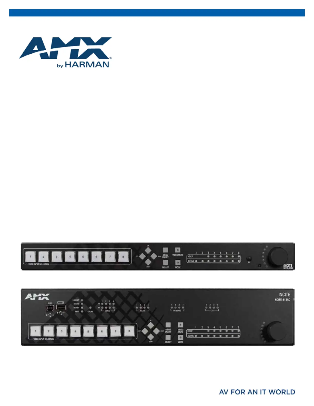
Produkt Specifikationer

Mærke: AMX
Kategori: Ikke kategoriseret
Model: NCITE-813A

Har du brug for hjælp?

Hvis du har brug for hjælp til AMX NCITE-813A stil et spørgsmål nedenfor, og andre brugere vil svare dig