INSTALLATION INSTRUCTIONS
AXSUB-FD1
AxxessInterfaces.com © COPYRIGHT 2025 METRA ELECTRONICS CORPORATION REV. 6/17/25 AXSUB-FD1
TOOLS REQUIRED
TABLE OF CONTENTS
Connections.................................................................2
Programming..............................................................3
Testing..........................................................................3
Specifications...............................................................3
Troubleshooting..........................................................4
• Crimping tool and connectors, or solder gun,
solder, and heat shrink • Tape • Wire cutter
• Zip ties • Multimeter
ATTENTION: With the key out of the ignition,
disconnect the negative battery terminal before
installing this product. nsure that all installation
connections, especially the air bag indicator
lights, are plugged in before reconnecting
the battery or cycling the ignition to test this
product.
NOTE: Refer also to the instructions included
with the aftermarket radio.
INTERFACE COMPONENTS
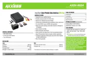
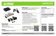
• AXSUB-FD1 interface
• AXDSPX-FD1 vehicle T-harness (LD-DSP-FD1)
• Bass knob (LD-BASSKNOB)
www.AxxessInterfaces.com
If the vehicle is equipped with Active noise
cancelation (ANC) microphones, they
will need to be bypassed. Please refer
to Axxessinterfaces.com for ANC bypass
harnesses offered for select vehicles.
INTERFACE FEATURES
Add-a-Sub Data Interface
Fits Select Ford Models 2006-2014
• Designed for amplified and non-amplified systems
• 2-channel non-fading 5V RMS output
• Fixed low-pass frequency of 234Hz
• 250mA remote turn-on output
• Bass knob included for level control of subwoofer amp
• Install done at radio location
• Micro “B” USB updatable
Visit AxxessInterfaces.com for more detailed
information about the product and up-to-date
vehicle specific applications.
www.MetraOnline.com
For Dash Disassembly Instructions, refer to
metraonline.com. Enter the year, make, and
model of the vehicle in the Vehicle Fit Guide
for Radio Install kits.