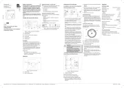
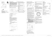
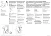
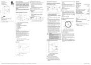
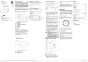
Berker 20292089 Manual

Berker Vægudtag 20292089

Læs gratis den danske manual til Berker 20292089 (2 sider) i kategorien Vægudtag. Denne vejledning er vurderet som hjælpsom af 2 personer og har en gennemsnitlig bedømmelse på 4.8 stjerner ud af 1.5 anmeldelser. Har du et spørgsmål om Berker 20292089, eller vil du spørge andre brugere om produktet?

Side 1/2
6LE007112C
Operating and
assembly instructions
Bedienings- en
montagehandleiding
z
i
Berker GmbH & Co. KG - Zum Gunterstal - 66440 Blieskastel/Germany - Telefon: + 49 6842/945-0 - Telefax: + 49 6842/945-4625 - www.berker.com - 6LE007112C - 12/2020
2029 20 ..
Room thermostat with swich
heating/cooling
Kamerthermostaat med schakelaar
verwarmen / koelen
Safety instructions
Electrical equipment may only be installed and
assembled by a qualifi ed electrician in accord-
ance with the relevant installation standards,
guidelines, regulations, directives, safety and
accident prevention regulations of the country.
Failure to comply with these instructions may
result in damage to the device, fi re or other
hazards.
These instructions are an integral component
of the product and must be retained by the end
user.
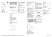
Design and layout of the device
(1)
(3)
(4)
(6)
(2)
(5)
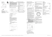
Bild 1: Design and layout of the device
(1) Thermostat insert
(2) Rocker switch
(3) Frame (not within scope of delivery)
(4) Centre plate
(5) Fastening screw
(6) Setting knob
Function
The thermostat controls the temperature in enclosed
spaces. It is controlled using the measured value of
the internal temperature sensor. The thermal re-cir-
culation (thermal resistor) achieves ecient control
during heating operation.
The thermostat possesses a switch, using which it is
possible to switch between the Heating and Cooling
control types.
Correct use
- Only suitable for indoor applications.
- Installation in wall box according to DIN49073
(deep box recommended)
Operation
(7)
(6)
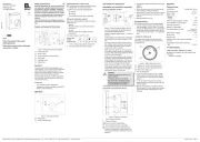
Bild 2: Operating elements
(6) Setting knob
(7) Switch heating/cooling
Switching heating or cooling mode
The printing of the heating/cooling slide switch is
designed for normally closed valves.
Switch the switch to the desired position.
Heating
Cooling
The selected operating mode is executed.
Setting the temperature setpoint
Specify the room temperature setpoint using the
setting knob (6):
- Heating:
When the setpoint is undershot, the device
switches on.
- Cooling:
When the setpoint is exceeded, the device
switches on.
The setting range is max. 5°C to 30°C.
Setting value
(scale)
2 3 5 6
Temperature [°C]
5 10 15 20 25 30
Table 1: Setting values of the setting knob
Turn setting knob to the desired setting.
Information for electricians
Installation and electrical connection
Selecting installation location
1,5 m
Bild 3: Recommended installation location
- An inside wall opposite the heating source is the
preferred installation location.
- Optimal installation height approx. 1.5 m above
the oor.
- Avoid installation on outside walls and draught
from windows or doors at the installation loca-
tion.
- The heated room air should be able to reach the
controller without hindrance. Do not mount the
controller within shelving units or behind curtains
and similar coverings.
- Extraneous heat a ects the control accuracy.
Avoid direct sunlight and do not install near televi-
sions, radios and heating appliances, lamps,
chimneys and heating pipes.
- Avoid mounting in combination with dimmers. If
necessary, maintain the greatest possible dis-
tance between the two devices. In the case of an
arrangement one above the other, the controller
must be arranged below the dimmer.
- When mounting the device in hollow walls, en-
sure that the controller is not exposed to any
outside heating or cooling from air draughts or
rising cables, also on the rear side.
DANGER!
Touching live parts can result in an
electric shock!
An electric shock can be lethal!
Disconnect the connecting cables
before working on the device and
cover all live parts in the area!
ç
Connecting and mounting the device
< ϑ
RF
Bild 4: Electrical connection
L Outer conductor (phase)
N Neutral conductor
Load connection heating/cooling
RF Thermal resistor thermal recirculation
The printing of the heating/cooling slide switch is
designed for normally closed valves. A maximum
of 5 valve drives may be connected to the device.
The N conductor must be connected to the
thermal re-circulation as a power supply, oth-
erwise large temperature variations should be
expected.
Connect the controller according to connection
diagram
(figure 4). Observe the terminal labelling.
Mount the rocker switch (2) in the appropriate
seat opening, according to the figure.
Attach frame (3) and fix it in the correct position
with the fastening screw (5) using the centre plate
(4).
Slip the setting knob (6) on.
Commissioning
The thermo-bimetal of the controller requires a
certain amount of time to adjust itself to the room
temperature. For this reason, the switching point
will deviate from the room temperature directly
after mounting. Switching point accuracy will only
occur after approx. 1 to 2 operating hours.
Limiting the setting range
The temperature setting range can be limited individ-
ually using 2 setting rings under the setting knob.
(8)
(9)
(10)
Bild 5: Setting limit on the centre plate
(8) Locking pin
(9) Setting ring, maximum temperature (red)
(10) Setting ring, minimum temperature (blue)
Pull the setting knob.
Pull out the locking pin (8) so that the setting
rings can be moved freely against each other.
To set the maximum setpoint, turn the red setting
ring (9) in an anticlockwise direction into the
required position.
To set the minimum setpoint, turn the blue setting
ring (10) in a clockwise direction into the required
position.
During setting, rough orientation for the setting
can be obtained from the printed scale.
Slip the setting knob on. In so doing, ensure that
the nose on the rotation axis is guided into the
appropriate seat recess in the controller.
Appendix
Technical data
Contact type Change-over contact
Temperature range 5-30 °C
Rated voltage AC 230 V
Rate current heating/cooling 5(2) A
Switching dierence temperature ~0.5 K
Temperature change speed
of the control path: max. 4 K/h
Degree of contamination 2
Permissible relative humidity max 95 %,
no condensation
Protection class (after complete installation
of cover) ΙΙ
Rated impulse voltage 4 kV
Connecting terminals screw terminals
- rigid 1 ... 2.5 mm²
Troubleshooting
Large temperature variations in control
No thermal re-circulation, as no N conductor was
connected.
Connect N conductor
z
Berker GmbH & Co. KG - Zum Gunterstal - 66440 Blieskastel/Germany - Telefon: + 49 6842/945-0 - Telefax: + 49 6842/945-4625 - www.berker.com - 6LE007112C - 12/2020
i
Veiligheidsinstructies
Inbouw en montage van elektrische apparatuur
mag alleen door een installateur worden uitge-
voerd conform de geldende installatienormen,
richtlij nen, voorschriften, bepalingen en onge-
vallenpreventievoorschriften van het betre en-
de land.
Wanneer deze handleiding niet in acht wordt
genomen, kan schade aan het apparaat, brand
of ander gevaar optreden.
Deze handleiding maakt deel uit van het pro-
duct en dient in het bezit van de eindgebruiker
te blij ven.
Opbouw van het apparaat
(1)
(3)
(4)
(6)
(2)
(5)
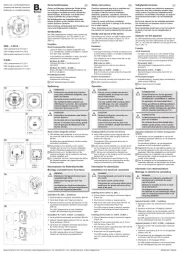
Afb. 1: Opbouw van het apparaat
(1) Thermostaat-inbouwelement
(2) Schakelwip
(3) Afdekraam (niet meegeleverd)
(4) Centraaldeel
(5) Bevestigingsschroef
(6) Regelknop
Functie
De thermostaat is bedoeld voor het regelen van de
temperatuur in gesloten ruimten. De regeling vindt
plaats over de gemeten waarde van de interne
temperatuurvoeler. Door de thermische terugvoer
(warmteweerstand) wordt bij de opwekking van
warmte een eciënte regeling bereikt.
De temperatuurregelaar bevat een schakelaar
waarmee kan worden omgeschakeld tussen de
regelingssoorten verwarmen en koelen.
Juiste toepassing
- Uitsluitend voor het gebruik binnenshuis.
- Montage in inbouwdoos conform DIN49073
(aanbeveling diepe doos)
Bediening
(7)
(6)
Afb. 2: Bedieningselementen
(6) Regelknop
(7) Schakelaar Verwarmen / koelen
Omschakelen verwarmen/koelen
De opschriften van de omschakelaar verwarmen/
koelen afgedrukt op stroomloos gesloten ventie-
len.
Schakel de schakelaar in de gewenste positie.
Verwarmen
Koelen
De gewenste modus wordt uitgevoerd.
Gewenste temperatuurwaarde instellen
Met de regelknop (6) wordt de gewenste waarde van
de kamertemperatuur ingesteld:.
- Verwarmen:
onderschrij den van de gewenste waarde
schakelt het apparaat in.
- Koelen:
overschrij den van de gewenste waarde scha-
kelt het apparaat in.
Het instelbereik bedraagt max. 5°C tot 30°C.
Instelwaarde
(schaal)
2 3 5 6
Temperatuur [°C]
5 10 15 20 25 30
Tabel1: Instelwaarden van de regelknop
Draai de regelknop naar de gewenste instelling.
Informatie voor de elektrotechnisch
installateur
Montage en elektrische aansluiting
Montageplaats kiezen
1,5 m
Afb. 3: Aanbevolen montageplaats
- Installatie op de binnenwanden tegenover de
verwarmingsbron verdient de voorkeur.
- Optimale montagehoogte ca. 1,5 m boven de
vloer.
- Vermij d montage op buitenwanden en tocht door
ramen en deuren op de montageplaats.
- De verwarmde ruimtelucht moet de regelaar on-
gehinderd kunnen bereiken. Thermostaat niet
tussen schappen of achter gordij nen en derge-
ke afdekkingen monteren.
- Externe warmte heeft een nadelige invloed op de
regelnauwkeurigheid. Directe zonnestralen, nabij -
heid van TV-, radio- en verwarmingsapparaten,
lampen, open haarden en verwarmingsbuizen
moeten worden vermeden.
- Vermij d montage in combinatie met dimmers.
Houd indien mogelij k een zo groot mogelij ke af-
stand tussen beide apparaten aan. Bij een op-
stelling boven elkaar moet de thermostaat onder
de dimmer worden geplaatst.
- Houd er bij montage in holle wanden rekening
mee dat ook de achterkant van de regelaar niet
wordt blootgesteld aan externe verwarming of
koeling.
GEVAAR!
Gevaar voor elektrische schokken bij
aanraking van onderdelen die onder
spanning staan!
Elektrische schokken kunnen de dood
tot gevolg hebben!
Voorafgaand aan werkzaamheden aan
het apparaat de aansluitleidingen
loskoppelen en spanningvoerende
delen in de omgeving afdekken!
ç
Apparaat aansluiten en monteren
< ϑ
RF
Afb. 4: Elektrische aansluiting
L Fasegeleider (fase)
N Neutrale geleider
Lastaansluiting verwarmen / koelen
RF Verwarmingsweerstand thermische terugkop-
peling
De opschriften van de omschakelaar verwar-
men/koelen afgedrukt op stroomloos gesloten
ventielen. Op het apparaat mogen maximaal 5
ventielaandrijvingen worden aangesloten.
Voor de voeding van de thermische terugvoer
moet de N-leider worden aangesloten, anders
treden grote temperatuurwisselingen op.
Reglar conform het aansluitschema aansluiten
(afb. 4). Let op de tekst op de klemmen.
Monteer de schakelwip (2) conform de afbeelding
in de betreende opening.
Plaats de afdekraam (3) en zet hem in de juiste
positie boven het centraaldeel (4) met een beves-
tigingsschroef (5) vast.
Regelknop (6) aanbrengen.
Inbedrij fstelling
Het thermische bimetaal van de regelaar heeft
enige tijd nodig om zich aan de kamertem-
peratuur aan te passen. Daarom zal direct na
de montage het schakelpunt afwijken van de
kamertemperatuur. De nauwkeurigheid van het
schakelpunt wordt pas na 1 tot 2 uur bedrijfsduur
bereikt.
Instelbereik begrenzen
Het instelbereik van de temperatuur kan individu-
eel worden begrensd met 2 instelringen onder de
regelknop.
(8)
(9)
(10)
Afb. 5: Instelbegrenzing op het centraaldeel
(8) Stopstift
(9) Instelring maximale temperatuur (rood)
(10) Instelring minimale temperatuur (blauw)
Trek de regelknop er af.
Trek de stopstift (8) zover uit dat de instelringen
vrij ten opzichte van elkaar verschoven kunnen
worden.
Draai voor het instellen van de maximale
gewenste waarde de rode instelring (9) met
een geschikt puntig voorwerp linksom naar de
gewenste positie.
Draai voor het instellen van de minimale ge-
wenste waarde de blauwe instelring (10) met
een geschikt puntig voorwerp rechtsom naar de
gewenste positie.
Bij het instellen is een grove oriëntatie voor de in-
stelling mogelijk aan de hand van de opgedrukte
schaal.
Regelknop aanbrengen. Let er hierbij op dat de
neus op de draaias in de betreende uitsparing
van de bevestiging in de regelaar gebracht wordt.
lage
Technische gegevens
Contactsoort wissel
Temperatuurbereik 5-30 °C
Nominale spanning AC 230 V
Nominale stroom verwarmen/koelen 5(2) A
Schakelverschil temperatuur ~0,5 K
Veranderingssnelheid temperatuur
van het regeltraject: max. 4 K/h
Vervuilingsgraad 2
Toelaatbare relatieve kamervochtigheid max. 95%,
geen condensatie
Beveiligingsklasse (na volledige
montage van de afdekking) II
Nominale impulsbestendigheids sterkte test 4 kV
Aansluitklemmen schroefklemmen
- star 1 ... 2,5 mm²
Hulp bij problemen
Grote temperatuurwisselingen bij de regeling
Geen thermische terugvoer omdat geen N-leiding is
aangesloten.
N-leider aansluiten


Produkt Specifikationer

Mærke: Berker
Kategori: Vægudtag
Model: 20292089

Har du brug for hjælp?

Hvis du har brug for hjælp til Berker 20292089 stil et spørgsmål nedenfor, og andre brugere vil svare dig


Vægudtag Berker Manualer
Berker

Berker 20297103 Manual

16 September 2025
Berker

Berker 20292089 Manual

16 September 2025
Berker

Berker 20297109 Manual

16 September 2025
Berker

Berker 168055 Manual

16 September 2025

Vægudtag Manualer

Nyeste Vægudtag Manualer

Setti+

Setti+ SP401M Manual

16 September 2025
Ikea

Ikea TRETAKT 005.565.13 Manual

16 September 2025
H-Tronic

H-Tronic HT1EPP Manual

14 September 2025
Elektrobock

Elektrobock TS06-E Manual

14 September 2025
LEDmaxx

LEDmaxx USB2201 Manual

9 September 2025
LEDmaxx

LEDmaxx USB2203 Manual

9 September 2025
Rocketfish

Rocketfish RF-HTS7723 Manual

9 September 2025
Heitronic

Heitronic Golv x2 Manual

8 September 2025
SurgeX

SurgeX PF-420 Manual

8 September 2025
Heitronic

Heitronic MINIMO Manual

8 September 2025