Broan 112 Manual
Broan
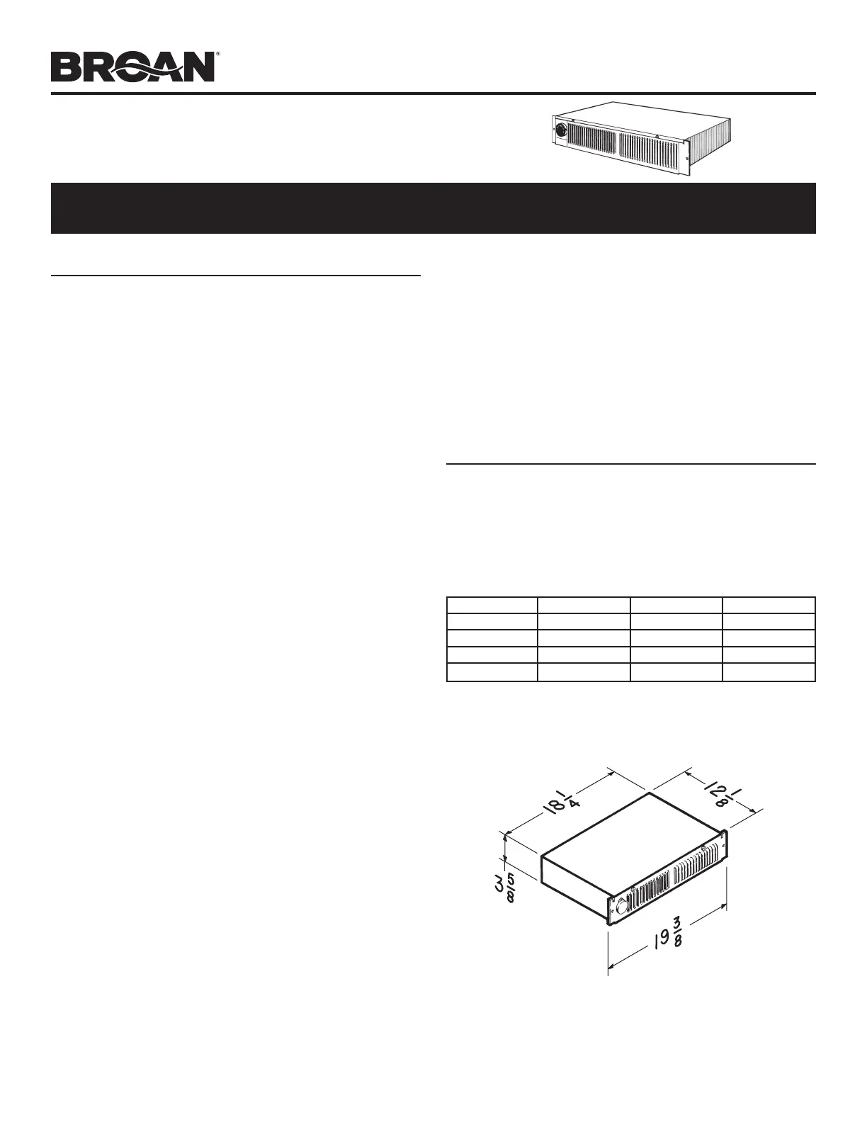
Varmeapparat
112
| Mærke: | Broan |
| Kategori: | Varmeapparat |
| Model: | 112 |
Har du brug for hjælp?
Hvis du har brug for hjælp til Broan 112 stil et spørgsmål nedenfor, og andre brugere vil svare dig
Varmeapparat Broan Manualer

2 September 2024

2 September 2024

2 September 2024

2 September 2024

2 September 2024

2 September 2024

2 September 2024

2 September 2024

1 September 2024

1 September 2024
Varmeapparat Manualer
- Adler
- Daewoo
- Camry
- Nobo
- Duro Pro
- Stanley
- Daikin
- Chauvet
- Brentwood
- Caso
- Renkforce
- AEG
- Steinel
- Beper
- Hayward
Nyeste Varmeapparat Manualer

11 December 2025

11 December 2025

11 December 2025

11 December 2025

10 December 2025

9 December 2025

8 December 2025

8 December 2025

8 December 2025

8 December 2025