Carrier AQUASNAP 30RAP Manual

Carrier Ikke kategoriseret AQUASNAP 30RAP

Læs gratis den danske manual til Carrier AQUASNAP 30RAP (84 sider) i kategorien Ikke kategoriseret. Denne vejledning er vurderet som hjælpsom af 6 personer og har en gennemsnitlig bedømmelse på 3.5 stjerner ud af 3.5 anmeldelser. Har du et spørgsmål om Carrier AQUASNAP 30RAP, eller vil du spørge andre brugere om produktet?

Side 1/84
Manufacturer reserves the right to discontinue, or change at any time, specifications or designs without notice and without incurring obligations.
Catalog No. 04-53300174-01 Printed in U.S.A. Form 30RAP-17SI Rev. A Pg 1 1-22 Replaces: 30RAP-16SI
Installation Instructions
CONTENTS
Page
SAFETY CONSIDERATIONS. . . . . . . . . . . . . . . . . . . . . . 1
INSTALLATION . . . . . . . . . . . . . . . . . . . . . . . . . . . . . . . . . . 2
Storage Recommendations . . . . . . . . . . . . . . . . . . . . . . 2
Step 1 — Place and Rig the Unit. . . . . . . . . . . . . . . . . . 2
•PLACING UNIT
•RIGGING
MOUNTING UNIT
Step 2 — Check Compressor Mounting . . . . . . . . . 18
Step 3 — Connect Cooler Fluid and
Drain Piping. . . . . . . . . . . . . . . . . . . . . . . . . . . . . . . . . . 18
•ALL UNITS
VICTAULIC COUPLING INSTALLATION
UNITS WITH FACTORY-INSTALLED
HYDRONIC PACKAGES
•AIR SEPARATION
Step 4 — Fill the Chilled Water Loop . . . . . . . . . . . . 34
WATER SYSTEM CLEANING
FILLING THE SYSTEM
•PUMP VFD
SENSORLESS CONTROL (CLOSED LOOP) —
ACTIVE SETUP 1
REMOTE SENSOR (CLOSED LOOP) —
ACTIVE SETUP 2
REMOTE CONTROLLER (OPEN LOOP) —
ACTIVE SETUP 3
PREPARATION FOR YEAR-ROUND OPERATION
FREEZE PROTECTION
PREPARATION FOR WINTER SHUTDOWN
Step 5 — Make Electrical Connections . . . . . . . . . . 45
POWER SUPPLY
•POWER WIRING
CONTROL POWER
Step 6 — Install Accessories . . . . . . . . . . . . . . . . . . . . 67
ELECTRICAL
Step 7 — Check Refrigerant Circuit . . . . . . . . . . . . . 67
LEAK TESTING
DEHYDRATION
REFRIGERANT CHARGE
BACnet Communication Option Wiring . . . . . . . . . 68
APPENDIX A (PRESSURE DROP CURVES). . . . . . 71
SAFETY CONSIDERATIONS
Installing, starting up, and servicing air-conditioning equip-
ment can be hazardous due to system pressures, electrical
components, and equipment location (roofs, elevated struc-
tures, etc.).
Only trained, qualified installers and service mechanics
should install, start up, and service this equipment (Fig. 1).
Untrained personnel can perform basic maintenance func-
tions such as cleaning coils. All other operations should be
performed by trained service personnel.
When working on the equipment, observe precautions in the
literature and on tags, stickers, and labels attached to the
equipment.
Follow all safety codes.
Wear safety glasses and work gloves.
Keep quenching cloth and fire extinguisher nearby when
brazing.
Use care in handling, rigging, and setting bulky equipment.
WARNING
Electrical shock can cause personal injury and death. Shut off
all power to this equipment during installation. There may be
more than one disconnect switch. Tag all disconnect locations
to alert others not to restore power until work is completed.
WARNING
DO NOT USE TORCH to remove any component. System
contains oil and refrigerant under pressure.
To remove a component, wear protective gloves and gog-
gles and proceed as follows:
a. Shut off electrical power to unit.
b. Recover refrigerant to relieve all pressure from sys-
tem using both high-pressure and low pressure ports.
c. Traces of vapor should be displaced with nitrogen
and the work area should be well ventilated. Refrig-
erant in contact with an open flame produces toxic
gases.
d. Cut component connection tubing with tubing cutter
and remove component from unit. Use a pan to catch
any oil that may come out of the lines and as a gage
for how much oil to add to the system.
e. Carefully unsweat remaining tubing stubs when nec-
essary. Oil can ignite when exposed to torch flame.
Failure to follow these procedures may result in personal
injury or death.
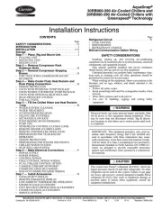
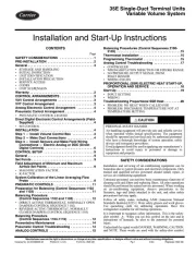
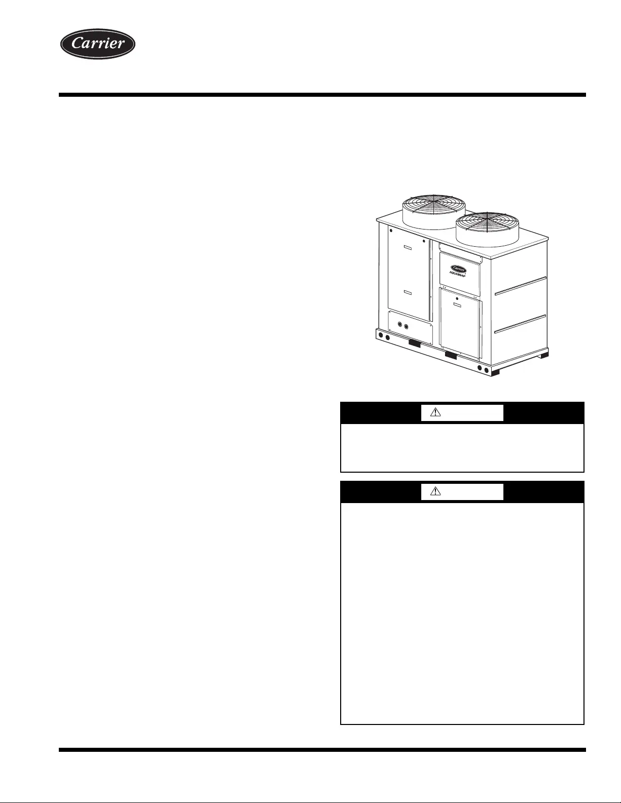
Fig. 1 — Typical 30RAP Unit (018-030 Shown)
AquaSnap
®
30RAP018-150 Air-Cooled Chillers and
30RAP011-060 Air-Cooled Chillers
with Greenspeed
®
Intelligence
with Puron
®
Refrigerant (R-410A)
50/60 Hz
2
INSTALLATION
Storage Recommendations —
The 30RAP air-
cooled chillers are designed for outdoor installations. At
times, a delay in construction or other factors require that a
unit be stored for a period of time prior to installation. The
following guidelines should be used for unit storage.
PROVIDE MACHINE PROTECTION — Place and store
the unit in an area that will protect it from vandalism, acciden-
tal contact with vehicles, falling debris or construction waste.
Ideally, do not remove the shipping protection such as the coil
protectors. This will provide additional protection for the unit.
The unit can be stored outdoors.
INSPECTION DURING STORAGE — To ensure faster
installation when the time comes, the following inspection
schedule is recommended:
Every 3 Months
The 30RAP units are shipped with a com-
plete operating charge of R-410A. Check each refrigerant cir-
cuit to be sure that there is positive pressure, at least 26 psig
(180 kPa) in the circuit. If a circuit is found to be without pres-
sure, contact a qualified refrigeration mechanic. The system
should be pressurized to find the leak. It should be repaired, de-
hydrated, and recharged with refrigerant. If a positive circuit
pressure was not found, the compressor oil should be changed
or at least sampled to determine if moisture is present. If mois-
ture is found in the compressor oil, the oil should be changed.
Every 6 Months
— Check the unit for damage, both physical
and from wildlife. Check the unit for nests from rodents, birds,
or insects. Depending on location, these organisms can cause
deterioration of components which may result in failure. Con-
sider an exterminator if necessary. If damage is found and it
will interfere with the installation, consider repairing the dam-
age before installation. Check the unit control box for signs of
moisture. If moisture is found, determine the entry path and
seal the leak.
Step 1 — Place and Rig the Unit
PLACING UNIT — Units are suitable for outdoor use only.
For 30RAP011-060 units, see Fig. 2. When parallel chillers
are aligned such that coils face each other, a minimum of
6 ft (1829 mm) separation is recommended. When the paral-
lel arrangement has only one coil drawing air from the space
between chillers, a minimum of 3.5 ft (1067 mm) is recom-
mended. When parallel chillers have no coils facing each
other (a back-to-back arrangement), be sure to maintain the
larger of the recommended service clearances associated
with each chiller (see the certified drawings). Due to NEC
(National Electric Code) regulations, a minimum clearance
of 4 ft (1219 mm) must be maintained on the side of the
chiller that has an electrical box. Chiller fan discharge must
be at least as high as adjacent solid walls. Installation in pits
is not recommended.
For 30RAP070-150 units, see Fig. 3. When chillers are ar-
ranged in parallel, a minimum of 10 ft (3048 mm) between
chillers is recommended. Acceptable clearance on the cooler
connection side or end opposite the control box of the unit can
be reduced to 3 ft (1 m) without sacrificing performance as
long as the remaining three sides are unrestricted. Acceptable
clearance on the side with a control box can be reduced to 4 ft
(1.3 m) due to NEC (National Electric Code) regulations, with-
out sacrificing performance as long as the remaining three
sides are unrestricted. Clearances between chillers in dual
chiller applications may be reduced to 6 ft (1.8 m) without sac-
rificing performance provided the remaining sides are unre-
stricted. For acceptable clearance with layout involving more
than 2 chillers, please contact application engineering.
These instructions cover installation of 30RAP011-150 air-
cooled liquid chillers. Refer to Fig. 4 and 5 for model number
to determine factory-installed options.
RIGGING Preferred method for rigging is with spreader
bars from above the unit. Use shackles in lifting holes. Rig at a
single point with 4 cables for size 011-115 units, 6 cables for size
130 and 150 units, or use spread bars. All panels must be in place
when rigging. See rigging label on unit for details concerning
shipping weights, distance between lifting holes, center of gravi-
ty, and lifting ring dimensions. See Tables 1-3 and Fig. 6 for
unit weights. See Tables 6 and 7 for physical data. See Fig. 7
and 8 for rigging label.
If overhead rigging is not possible, place chiller on skid or
pad for rolling or dragging. When rolling, use a minimum of
3 rollers. When dragging, pull the pad. Do not apply force to
the unit. When in final position, raise from above to lift unit
off pad.
CAUTION
DO NOT re-use compressor oil or any oil that has been
exposed to the atmosphere. Dispose of oil per local codes
and regulations. DO NOT leave refrigerant system open to
air any longer than the actual time required to service the
equipment. Seal circuits being serviced and charge with
dry nitrogen to prevent oil contamination when timely
repairs cannot be completed. Failure to follow these proce-
dures may result in damage to equipment.
CAUTION
All panels must be in place when rigging. If they are not,
damage to unit could result.
6 ft
(1.8 m)
MINIMUM*
3.5 ft (1.1 m)
MINIMUM†
* Minimum for when coils face each other. Less clearance is
required in other configurations.
† Clearance of 3.5 ft is required when a coil faces the wall. When
there is no coil facing the wall, see the certified drawing for the
required service clearance.
a30-4873
Fig. 2 — 30RAP011-060 Multiple Unit Separation
10 ft
(3 m)
MINIMUM
6 ft (1.8 m)
MINIMUM
a30-4904
Fig. 3 — 30RAP070-150 Multiple Unit Separation


Produkt Specifikationer

Mærke: Carrier
Kategori: Ikke kategoriseret
Model: AQUASNAP 30RAP

Har du brug for hjælp?

Hvis du har brug for hjælp til Carrier AQUASNAP 30RAP stil et spørgsmål nedenfor, og andre brugere vil svare dig