Manufacturer reserves the right to discontinue, or change at any time, specifications or designs without notice and without incurring obligations.
Catalog No. 04-53500450-01 Printed in U.S.A. Form No. 50WT-1SI Pg 1 3-25 Replaces: NEW
Installation, Start-Up, and
Service Instructions
CONTENTS
Page
SAFETY CONSIDERATIONS . . . . . . . . . . . . . . . . . . . 2
GENERAL . . . . . . . . . . . . . . . . . . . . . . . . . . . . . . . . . . . 3
PRE-INSTALLATION . . . . . . . . . . . . . . . . . . . . . . . . . . 3
•INSPECTION
• STORAGE
INSTALLATION . . . . . . . . . . . . . . . . . . . . . . . . . . . . . . 6
Step 1 — Check Jobsite . . . . . . . . . . . . . . . . . . . . . . . 6
• HORIZONTAL UNITS
• VERTICAL UNITS
• INSTALLATION GUIDELINES (ALL UNITS)
Step 2 — Check Unit . . . . . . . . . . . . . . . . . . . . . . . . . . 6
•INSPECT UNIT
Step 3 — Locate Unit . . . . . . . . . . . . . . . . . . . . . . . . 10
• PROTECTION
Step 4 — Mount the Unit . . . . . . . . . . . . . . . . . . . . . . 10
• DUCT FLANGES
• HORIZONTAL UNITS
• VERTICAL UNITS
Step 5 — Check Duct System . . . . . . . . . . . . . . . . . 11
• HORIZONTAL SUPPLY AIR CONFIGURATION
CONVERSION
Step 6 — Install Condensate Drain . . . . . . . . . . . . . 13
• HORIZONTAL UNITS
• VERTICAL UNITS
Step 7 — Pipe Connections . . . . . . . . . . . . . . . . . . . 13
• WATER QUALITY GUIDELINES
• INSTALLING SUPPLY AND RETURN HOSE KIT
• UNITS WITH BOILERLESS HEAT CONTROL
• UNITS WITH HOT WATER GENERATOR OPTION
(HEAT RECOVERY PACKAGE/DESUPERHEATER)
• INITIAL START-UP
• UNITS WITH WATERSIDE ECONOMIZER
Step 8 — Wire Field Power Supply . . . . . . . . . . . . . 17
• HIGH VOLTAGE WIRING
• ELECTRIC HEATER
• LOW VOLTAGE, CONTROL WIRING
• ECM INTERFACE THERMOSTAT CONNECTIONS
• THERMOSTAT AND DDC SENSORS
• ADDITIONAL CONTROLS OPTIONS WIRING
Step 9 — Configure Unit Control Components . . . 21
• UNIT PROTECTION MODULE (UPM)
UPM Standard Safeties and Alarms . . . . . . . . . . . . 22
• HI AND LOW REFRIGERANT PRESSURE
PROTECTION
• WATER COIL FREEZE PROTECTION
• AIR COIL FREEZE PROTECTION
• HIGH CONDENSATE LEVEL SHUTDOWN
• INTELLIGENT ALARM RESET
• HARD LOCKOUT RESET
• OPTION CARD
PRE-START-UP . . . . . . . . . . . . . . . . . . . . . . . . . . . . .35
System Checkout . . . . . . . . . . . . . . . . . . . . . . . . . . . .35
• CLEAN AIR COIL
• CONSTANT AIRFLOW (ECM) MOTOR
System Flushing and Filling . . . . . . . . . . . . . . . . . . .38
System Flow . . . . . . . . . . . . . . . . . . . . . . . . . . . . . . . .38
• FLOW VERIFICATION
• FLOW REGULATION
• ANTIFREEZE
• FREEZE PROTECTION SELECTION
•START-UP
Operating Limits . . . . . . . . . . . . . . . . . . . . . . . . . . . .40
• ENVIRONMENT
• POWER SUPPLY
• UNIT STARTING CONDITIONS
Start-Up Procedure . . . . . . . . . . . . . . . . . . . . . .41
• COOLING MODE START-UP
• HEATING MODE START-UP
OPERATION . . . . . . . . . . . . . . . . . . . . . . . . . . . . . . . .45
Power Up Mode . . . . . . . . . . . . . . . . . . . . . . . . . . . . .45
Unit Protection Module (UPM) . . . . . . . . . . . . . . . . .45
Option Card . . . . . . . . . . . . . . . . . . . . . . . . . . . . . . . .45
Sequence of Operation of Units Without DDC
Controller . . . . . . . . . . . . . . . . . . . . . . . . . . . . . . . . . 45
• STANDBY
• COOLING
• HOT GAS REHEAT WITH OPTION CARD (OPTIONAL)
• WATERSIDE ECONOMIZER WITH OPTION CARD
(OPTIONAL)
• AUXILIARY ELECTRIC HEAT (OPTIONAL)
• TWO-POSITION MOTORIZED ISOLATION VALVE
(2-WAY SOLENOID VALVE) (OPTIONAL)
• BOILERLESS HEAT WITH OPTION CARD
(OPTIONAL)
• DIFFERENTIAL PRESSURE SWITCH / FLOW SWITCH
(OPTIONAL)
• REFRIGERANT LEAK DETECTION SYSTEM
(OPTIONAL)
• COMPRESSOR RELAY (OPTIONAL)
• PUMP/VALVE RELAY (OPTIONAL)
Sequence of Operation for Units with TruVu DDC
Controller . . . . . . . . . . . . . . . . . . . . . . . . . . . . . . . .47
• SCHEDULING
• INDOOR FAN
• COOLING OPERATION
• HEATING OPERATION
• WATERSIDE ECONOMIZER
Indoor Air Quality and Demand Control Ventilation . .50
• COMPRESSOR STATUS
• DEMAND LIMITING
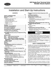
Aquazone™
50WT 024-070
Two-Stage High Efficiency Water Source Heat
Pumps with Puron Advance™ Refrigerant (R-454B)