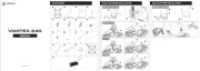
Daikin EWWQ025KCW1N Manual


Læs gratis den danske manual til Daikin EWWQ025KCW1N (36 sider) i kategorien Computer køling komponent. Denne vejledning er vurderet som hjælpsom af 3 personer og har en gennemsnitlig bedømmelse på 4.3 stjerner ud af 2 anmeldelser. Har du et spørgsmål om Daikin EWWQ025KCW1N, eller vil du spørge andre brugere om produktet?

Side 1/36
Water to water heat pump units with scroll compressors
EWWQ~KC/ EWLQ~KC
Original Instructions
REV
03
Date
08/2023
Supersedes
D-EOMHP01501-22_02EN
Operating Manual
D-EOMHP01501-22_03EN
D-EOMHP01501-22_03EN 2/36
Contents
1. SAFETY CONSIDERATIONS ..........................................................................................................................................3
1.1. General ..................................................................................................................................................................................................3
1.2. Before switching the unit ......................................................................................................................................................................3
1.3. Avoid electrocution ...............................................................................................................................................................................3
2. GENERAL DESCRIPTION ...............................................................................................................................................4
2.1. Basic Information ..................................................................................................................................................................................4
2.2. Controller Operating Limits...................................................................................................................................................................4
2.3. Controller Architecture ..........................................................................................................................................................................4
2.4. Controller maintenance ........................................................................................................................................................................4
2.5. Embedded Web Interface (Optional) ...................................................................................................................................................5
2.6. Application Save and Reset .................................................................................................................................................................5
3. WORKING WITH THIS UNIT ...........................................................................................................................................6
3.1. Unit Interface .........................................................................................................................................................................................6
3.1.1. Icons Description ............................................................................................................................................................................7
3.2. Insert Password ....................................................................................................................................................................................7
3.3. Chiller On/Off ........................................................................................................................................................................................7
3.3.1. Keypad On/Off ................................................................................................................................................................................8
3.3.2. Scheduler........................................................................................................................................................................................8
3.3.3. Network On/Off ...............................................................................................................................................................................9
3.3.4. Unit On/Off Switch..........................................................................................................................................................................9
3.4. Water Setpoints ..................................................................................................................................................................................10
3.5. Unit mode ............................................................................................................................................................................................11
3.5.1. Heat/Cool Mode ...........................................................................................................................................................................11
3.6. Pumps and Variable Flow ..................................................................................................................................................................11
3.6.1. Fixed Speed .................................................................................................................................................................................12
3.6.2. DeltaT............................................................................................................................................................................................12
3.7. Network Control ..................................................................................................................................................................................13
3.8. Thermostatic Control ..........................................................................................................................................................................13
3.8.1. Thermostatic Source Control .......................................................................................................................................................15
3.8.1.1. Entering Water Temperature Control ................................................................................................................................15
3.8.1.2. Leaving Water Temperature Control.................................................................................................................................15
3.9. External Alarm.....................................................................................................................................................................................16
3.10. Unit Capacity .......................................................................................................................................................................................17
3.11. Power Conservation ...........................................................................................................................................................................17
3.11.1. Setpoint Reset ..............................................................................................................................................................................17
3.11.1.1. Setpoint Reset by 0-10V signal .........................................................................................................................................18
3.11.1.2. Setpoint Reset by DT .........................................................................................................................................................18
3.12. Controller IP Setup .............................................................................................................................................................................18
3.13. Daikin On Site .....................................................................................................................................................................................19
3.14. Date/Time ............................................................................................................................................................................................20
3.15. Master/Slave .......................................................................................................................................................................................20
3.16. Customer Unit Configuration ..............................................................................................................................................................21
3.17. Three-way valve..................................................................................................................................................................................22
3.17.1. PID calibration ..............................................................................................................................................................................23
3.18. Water Reversing Valve .......................................................................................................................................................................23
3.18.1. Automatic Mode ...........................................................................................................................................................................23
3.18.2. Manual mode ................................................................................................................................................................................24
3.19. Connectivity Kit & BMS Connection...................................................................................................................................................24
3.20. Smart Grid Box and Energy Monitoring .............................................................................................................................................25
3.20.1. Additional customer configuration ...............................................................................................................................................25
3.20.2. BEG SG Ready & Energy Monitoring ......................................................................................................................................26
3.20.3. Energy Monitoring Values............................................................................................................................................................26
3.21. Additional HMI Parameters Navigation Table ...................................................................................................................................27
3.22. About Chiller ........................................................................................................................................................................................27
3.23. HMI Screen Saver...............................................................................................................................................................................27
3.24. Generic Controller Operation .............................................................................................................................................................28
3.25. HMI Parameters Navigation Table.....................................................................................................................................................28
4. ALARMS AND TROUBLE SHOOTING ..........................................................................................................................33
4.1. Alarms List: Overview .........................................................................................................................................................................33
4.2. Troubleshooting ..................................................................................................................................................................................34
List of tables
Graph 1 Compressors start-up sequence - Cool mode ................................................................................................... 14
Graph 2 External signal 0-10V vs Active Setpoint - Cooling mode(left)/ Heating mode(right) ........................................ 18
Graph 3 Evap ∆T vs Active Setpoint - Cooling mode(left)/ Heating mode(right) ............................................................. 18


Produkt Specifikationer

Mærke: Daikin
Kategori: Computer køling komponent
Model: EWWQ025KCW1N

Har du brug for hjælp?

Hvis du har brug for hjælp til Daikin EWWQ025KCW1N stil et spørgsmål nedenfor, og andre brugere vil svare dig


Computer køling komponent Daikin Manualer

Computer køling komponent Manualer

Nyeste Computer køling komponent Manualer