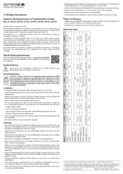
Draper Profile Manual


Læs gratis den danske manual til Draper Profile (3 sider) i kategorien Projektionsskærm. Denne vejledning er vurderet som hjælpsom af 46 personer og har en gennemsnitlig bedømmelse på 3.5 stjerner ud af 23.5 anmeldelser. Har du et spørgsmål om Draper Profile, eller vil du spørge andre brugere om produktet?

Side 1/3
i
i
iii
Assembly Instructions
Profile Permanently Tensioned Projection Screen by Draper
Copyright © 2015 Draper Inc. Form Profile_Inst15 Printed in U.S.A.
If you encounter any difficulties installing or servicing your Profile screen,
call your dealer or Draper, Inc., Spiceland, Indiana, (765) 987-7999.
Hardware and Parts List
Frame Preparation
Clean area and place frame assembly pieces face down. Insert corner
brackets into the first (i) aluminum frame extrusions. For easier assembly
insert the inner connectors first.
Repeat on the opposite end of the first extrusion (i) and slide the third (iii)
frame extrusion into place (see Fig. 3).
ii
i
Frame Extrusions - 4 Corner Bra ets - 8ck
Plastic Tubing - 4
1/8 Allen
Wrench - 1
BACK
FRONT
Viewing Surface - 1
Trim ame Fr
Extrusions - 4
Wall Bra ets - 2ck
#8 Screws
Surface Retention
Extrusions - Se lvera
(Continued on Page 2)
Patented by Draper, Inc., U.S. Patent Nos. 6,785,047; 7,113,332; and 7,369,310.
Caution
1 Read instructions through completely before proceeding.
2 Follow instructions carefully.
Installation contrary to instructions invalidates warranty.
3 Screen should be accessible for complete removal should fabric
become damaged or should other service be required.
4 Screen should be installed level (using a carpenters level).
5 Nothing should be fastened to screen frame or viewing surface.
6 Make sure you have received all parts (see parts list below and
exploded diagram on page 3).
7 Tools Required:
1
/
8
" Allen wrench (included); #2 Phillips screwdriver.
Flat blade screwdriver or small putty knife.Optional tools:
8 Installer is responsible for providing appropriate hardware for mounting.
9
Draper recommends using two people for assembly and installation.
When lifting assembled screen, do not lift at only one corner; lift at both
corners. Lifting by one corner could result in damage to the screen
frame, especially on large screens.
The ideal temperature range for assembling permanently tensioned
screens to prevent damaging the surface is 68°-78° F (20°-2 C).
Assembling below recommended temperatures may damage surface
and void warranty.
NOTE: Screen has been thoroughly inspected and tested at factory and
found to be operating properly prior to shipment.
Next, insert the remaining corner brackets into the fourth (iv) frame
extrusion. Then slide the brackets and extrusion into the three assembled
frame extrusions (see Fig 4).
iv
iii
i
ii
When all four corners are secure, tighten the setscrews on corner
brackets with provided Allen wrench (see Fig. 5).
Please Note: If corner brackets do not slide into frame extrusions, make sure
that setscrews are backed out enough to allow proper clearance.
Slide second (ii) aluminum frame extrusion over exposed portion of inner
connectors, forming a right angle. (see Fig. 2).
Profile by Draper Page 2 of 3
Slide Surface
Retention
Extrusion
Over Plastic
Tubing
BACK
Back of
Viewing Surface
Surface to Frame Assembly
Place frame face down, in the center of the viewing surface (see Fig. 10).
Insert opposite side of surface to notch #1 of frame extrusion.
Repeat steps 11-12 with remaining edges of surface.
Ensure surface retention extrusions are evenly spaced in tension slots on
all 4 edges of surface, resulting in a flat viewing surface (see Fig. 14).
If additional tension is desired or required over time, adjust surface one
edge at a time to tension notch #2.
Surface Preparation
Move assembled frame out of the way. Unroll the viewing surface with the
provided foam packing material. Lay them together on a smooth/clean
surface with the folded side of the hem visible (back side up).
Insert plastic tubing
inside pocket formed
by hem on all 4 edges
of viewing surface (see Fig. 7).
Carefully slide surface retention extrusions (flat edge visible) along
hem and onto surface on all 4 edges of fabric (see Fig. 8).
Verify that all surface retention extrusions are installed with flat edge
visible and are evenly spaced on surface material (see Fig. 9).
BACK
BACK
Back of
Viewing Surface
Back of
Viewing Surface
Insert
Plastic Tubing
into Hem tPocke
W
R
A
P
F
A
B
R
I
C
A
R
O
U
N
D
Caution:
Do not allow fabric to snag
on end of extrusion. If the
screen fabric is not parallel
with the surface retention
extrusion, then it may slit
and tear during installation.
Please Note: To make this step
easier, pinch the end of the pocket
closed before sliding it into the
surface retention extrusion.
Back of
Viewing Surface
Beginning in a corner, grab surface retention extrusion and wrap fabric
around the frame. Pull fabric towards the center of the frame and hook
into notch #1 on corresponding side of frame extrusion (see Fig. 11).
Back of
Viewing Surface
Back of
Viewing Surface
Please Note: It is not necessary to adjust more than one edge at a time
to increase surface tension.
Figure
Figure
Figure
Figure
Figure
(765) 987-7999
www
.draperinc.com
Figure
Caution: Draper strongly recommends using the provided foam packing
material as a protective barrier between the viewing surface and the work
area. This will help to ensure that the viewing surface is not damaged during
the assembly process.


Produkt Specifikationer

Mærke: Draper
Kategori: Projektionsskærm
Model: Profile

Har du brug for hjælp?

Hvis du har brug for hjælp til Draper Profile stil et spørgsmål nedenfor, og andre brugere vil svare dig