Contents
1 Application
2 Features
3 Controls
4 Functional description
4.1 Radio link set up –switched output
4.2 Testing range of radio link
4.3 Deleting radio links
4.4 Determining active links
4.5 Use of INSTAT 868-r timer thermostat (master - slave)
4.6 Alarm signal
4.7 Faults in radio link
4.7.1 Duplicate addressing
4.7.2 Short-term failures of transmitted signal
4.7.3 Extended failures of transmitted signal
4.8 Connection of thermal actuators normally open
4.9 Pump logic
4.10 Valve protection
4.11 Valve test
4.12 Heating/cooling changeover
4.13 Excluding rooms from cooling
4.14 Dew-point shutdown
4.15 Power failure
4.16 Reset
4.17 Lamp functions
5 Timer description
5.1 Settings
5.2 Setting the year and day of the week
5.3 Setting the month and day
5.4 Setting the time
5.5 Setting the party time function
5.6 Setting the holiday function
5.7 Setting time profiles for individual rooms
5.8 Setting profile No. 6
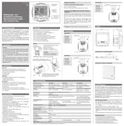
6 Installation / start-up
6.1 External antenna
6.2 What to do if …
7 Technical data
8 Brief manual
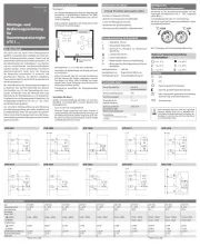
9 Circuit diagrams and examples
1. Application
This unit from the INSTAT 868 family converts information from
the INSTAT 868-r transmitter into control signals for the valves.
Additional functions allow the temperature to be altered for a
preset period of time.
2. Features
General:
• Ready to plug in to a 230 V power socket.
• Backlit display
• 230 V thermal actuators are directly connectable
(a separate version is available for 24V thermal actuators)
• Heating/cooling changeover using an external signal 230V
• Cooling shutdown at dew-point using an external signal (using
mains power signal or a directly connected dew-point sensor)
• Pump logic module, potential-free (recirculating pump shut
down if all valves are closed)
• Valve testing function
• Valve/pump protection (prevents jamming)
• Programming is possible even with cover removed (only if the
device is dis connected from mains)
Timer
• 8-channel timer for up to 8 time zones
• Preset real-time timer, no setting required
• Automatic summer/winter time changeover
• 6 time profiles, one variable
• Holiday function (reduction for a maximum of 199 days)
• Party function (‘comfort’ setting for a maximum of 23 hours)
Warning!
The unit must only be opened by a qualified electrician and
should be installed in accordance with the circuit diagram shown
on the unit and in compliance with these instructions. All valid
health and safety regulations must also be complied with.
This is an electronic device that is mounted in a switch cabinet to
control thermostats and valves. It is to be used only in dry rooms
and enclosed spaces where normal ambient conditions apply.
The device confirms to EN 60730, it works according operating
principle 1C
Radio communication
• 8 reception channels in one casing
• Master/slave function (master timer thermostat specifies
switching times, not the integrated timer)
• One transmitter can control several reception channels
• Transmitter has an auto-learn address setting using learning
mode
• External antenna can be connected (special variants)
• A signal lamp for each output displays relay status, faults etc.
• Alarm sounds if a fault is detected
• Monitoring of valid addresses
• Transmitter monitoring (if nothing is received from the trans-
mitter for a long period, for instance if the battery is flat), the
output is switched on for 30% of the time and the signal lamp
flashes.
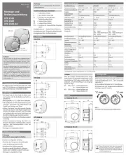
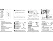
3. Controls
Room 1 … Room 8 Radio displays for rooms
On = relay energized, see 4.17
Flashing = fault, see 4.7
R1… R8 Display of ‘comfort’ or reduced
temperature for room
Moon = reduced temperature
No moon = ‘Comfort’ temperature
1…7 Weekday
MODE Operating mode selection
-/+ Increasing/decreasing set values
OK Confirm
PCooling active
®Dew-point identified
ê‘Comfort’ temperature (programming)
ëReduced temperature (programming)
lParty function
ßHoliday function
Standard display:
• Actual day of week (1 = Monday)
• Time
• Rooms with reduced temperature (here R1, R3, R5, R7)
If programming is to take place with the cover removed (only the
electrician must must perform this work), pull the flap-strip cable
off the load stage and press the OK button briefly until the dis-
play appears.
4. Functional description
The INSTAT 868-a8U receiver converts the radio signals from the
INSTAT 868-r… transmitter into control signals for electrical con-
sumers such as thermal actuators. The consumers are switched by
relays, with signal lamp to display the switched status in each
case.
For relay switching behaviour, see ‘Functional description’ in
transmitter installation instructions.
Room temperatures can be influenced by varying the time set-
tings at the built-in 8-channel timer.
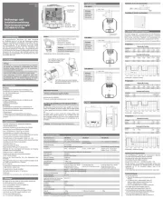
4.1 Radio link set-up – switched output
Up to eight transmitters control either one or several
‘Heating/cooling ON/OFF’ channels (1 … 8) (channel 8 may be il-
luminated, see 4.9).
One or several thermal actuators can be connected to each out-
put. For an example, see Fig. 1, 2.
Only the INSTAT 868-r1 (without timer) follows the time profile
of this receiver in the automatic mode.
The radio link is set up in the following steps:
a) Select the ‘Learning mode’ at the transmitter for the desired
room (see transmitter operating instructions).
b) At the receiver, set the desired channel to the learning mode
as follows:
MODE button press until L is displayed.
Channels already ‘learned’ can be seen at the
lamps and the display.
Press OK Lamp for room 1 flashes.
Press until the lamp for the desired room flashes.-/+
Press OK to start the learning process.
The display runs up at one-second intervals.
When the transmitter has been identified, the
corresponding signal lamp remains on and the dis-
play shows an arrow at the corresponding room.
If the same lamp starts to flash again, this is the
radio range test mode.
For this test, continue at Item 4.2.
Stop the learning mode at the transmitter.
To ‘learn’ the next room, carry out step a) and
select the appropriate channel at the receiver.
To allocate several reception channels to the
same transmitter, leave the transmitter in the
learning mode and ‘learn’ the relevant channels
one after the other.
Press MODE to return to the standard operating status.
Notes:
• The function is interrupted automatically if no button is
pressed for 10 minutes -> return to standard status
• Each channel needs about 30 seconds’ learning time.
• Learning at channel 8 shuts down the pump logic.
• One transmitter can control several reception channels
(several valves per transmitter).
4.2 Testing range of radio link
To determine the range of the radio link, establish the radio link
for the desired channel. Carry out step 4.1.
The signal lamp for the channel is illuminated.
Hold the transmitter and move away until the lamp begins to
flash again. At this point, the maximum range has been exceeded.
Stop the learning mode at the transmitter.
Note: The radio link is re-learned with this function.
4.3 Deleting radio links
To delete all radio links:
Press MODE until dEL is displayed.
The channels that have been learned will light
up.
Press OK dEL flashes.
Press OK to delete all channels.
The menu will return to the standard status.
4.4 Determining active links
See 4.1 ‘Radio link set-up’, Item b).
4.5 Use of INSTAT 868-r timer thermostat
(master - slave)
If learning of a timer thermostat (master) is carried out all the
downstream channels (slaves) follow the master unit’s switching
signals. The timer in this receiver is not used for these channels.
The reduced-temperature arrows indicate when the master and
slaves have reduced the temperature to the reduced value.
If, for example, the timer thermostat (master) has been learned at
channel 4, and channels 5, 6, 7, 8 have no timer (slaves), the slaves
at channels 5, 6, 7, 8 will follow the timer profile (temperature
lowering times) of the master at channel 4. For an example, see
Fig. 3.
Only slaves in the automatic operating mode follow the master
settings.
If the master develops a fault, the slaves’ reception channels re-
spond to the ‘comfort’ temperature setting at these control de-
vices.
4.6 Alarm signal
The alarm takes the form of an audible signal (only between 10 h
and 20 h).
If the OK button is pressed while the alarm is sounding, the audi-
ble warning is switched off until the fault has been rectified. The
alarm signal is heard again if a further fault develops.
4.7 Faults in radio link
If faults occur, they set off the alarm.
The signal lamp for the affected channel flashes and an audible
warning is heard if appropriate.
4.7.1 Duplicate addressing
“Err1” is displayed, the affected channel flashes and the warning
signal is heard. Eliminate this fault by re-learning one of the two
transmitters. The output is switched to 30 % of the set value.
4.7.2 Short-term failures of transmitted signal
If no control signal is received from the transmitter for a period
between 1 and 10 hours, the signal lamp flashes emits a series of
short single flashes (no audible warning signal). The output is
switched to 30 % of the set value. If the transmitted signal returns,
the alarm is discontinued automatically.
4.7.3 Extended failures of transmitted signal
If no control signal is received from the transmitter for a period
of more than 10 hours, the signal lamp flashes emits a series of
short single flashes and the warning signal is heard. The output is
switched to 30 % of the set value. If the transmitted signal returns,
the alarm is discontinued automatically.
Notes:
• The audible warning signal can be switched off permanently;
see 4.6.
• The audible alarm signal is only heard between 10 h and 20 h.
Applicable to all types of fault:
• Switch operation: if one output has a fault, the others are not
affected.
• Pump logic: in an alarm situation, the pump runs continuously
(even of only one transmitter has failed).
Installation instructions and
operating manual for the 8-channel
radio receiver with 8-channel timer
Instat 868-a8U / 230
U 468 931 003 218-01