Emko EPR-3790 Manual
Emko
Ikke kategoriseret
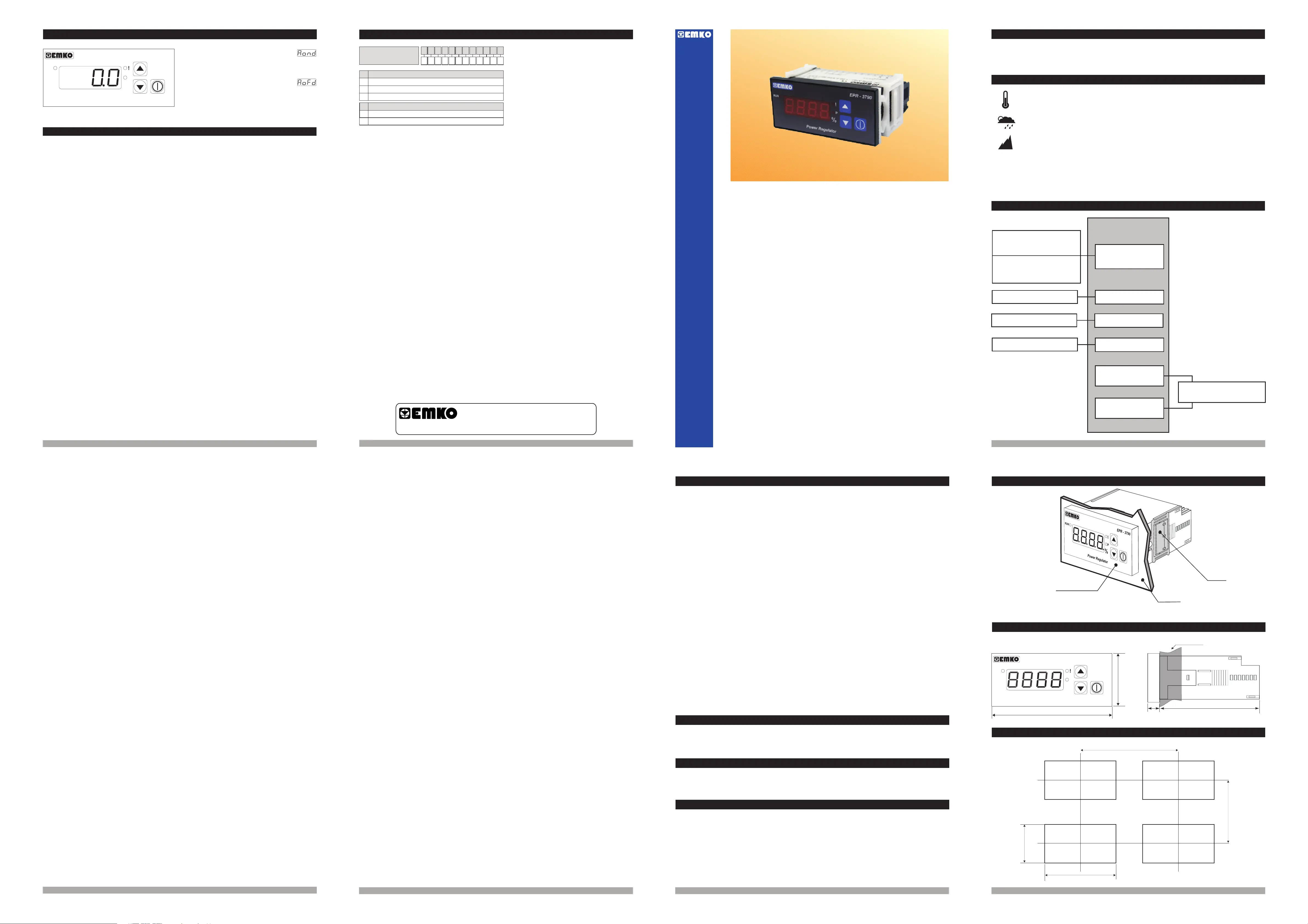
EPR-3790
| Mærke: | Emko |
| Kategori: | Ikke kategoriseret |
| Model: | EPR-3790 |
Har du brug for hjælp?
Hvis du har brug for hjælp til Emko EPR-3790 stil et spørgsmål nedenfor, og andre brugere vil svare dig
Ikke kategoriseret Emko Manualer
8 September 2025
8 September 2025
8 September 2025
8 September 2025
8 September 2025
8 September 2025
8 September 2025
8 September 2025
8 September 2025
7 September 2025
Ikke kategoriseret Manualer
- Revlon
- ZCover
- SuperFish
- ClipEyz
- JLCooper
- LodeStar
- Sure-Fi
- WAGAN
- Eldom
- Joby
- MPM
- Bauhn
- Phil & Teds
- ESKA
- ProUser
Nyeste Ikke kategoriseret Manualer
5 November 2025
5 November 2025
5 November 2025
5 November 2025

5 November 2025
5 November 2025
5 November 2025
5 November 2025
5 November 2025
5 November 2025