Copyright 2023 EtherWAN Systems, Inc. All Rights Reserved 03/06/2023
EX61000A | Hardened Managed Ethernet Switch
Unpacking
Unpack the items. Your package should include one EX61000 Series hardened
managed switch and one console cable.
If the device is missing or damaged, notify your EtherWAN
representative. If possible, save the carton and packing
material in case you need to ship or store the switch in the
future.
www.etherwan.com
Equipment Needed
▪ Category 5 or better cable for RJ-45 ports
▪ Appropriate fiber cables for fiber ports
▪ Appropriate SFP cable for SFP ports
▪ Personal computer with a DB-9 straight cable
Select a Location
▪ Indoor use only, DIN Rail, wall-mount, rack, or cabinet.
▪ Installation altitude should be less than 2000 meters.
▪ Identify a power source within 6 feet (1.8 meters).
▪ Choose a dry area with ambient temperature between -10 and 60 ºC (14
and 140ºF). Operational humidity range: 5% to 95%, non-condensation
▪ The product is open type. Be sure there is adequate airflow. (in an enclosure
or industrial panel)
▪ The Ethernet switch should be mounted in an industrial control panel with
ambient temperature not exceeding 75 degrees C.
Connect to the Data Ports
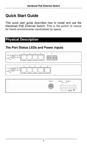
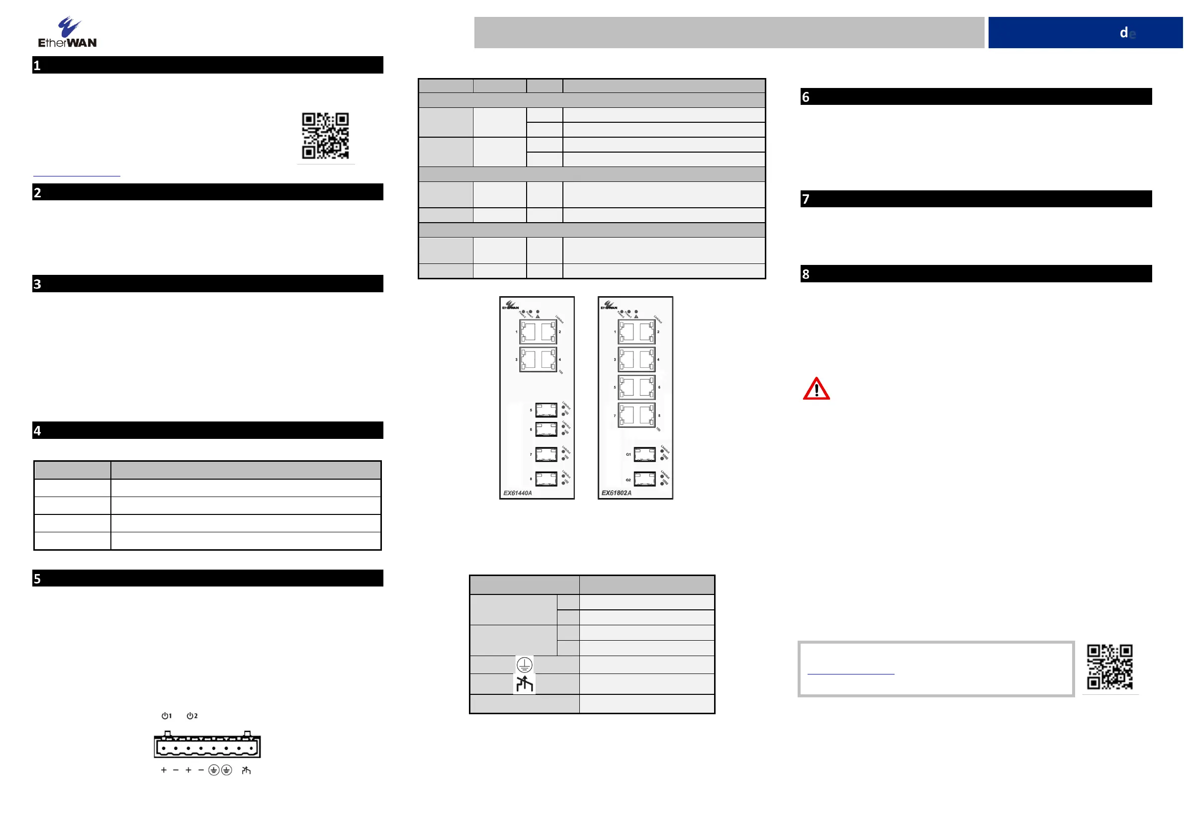
Depending on the model, your switch can have the following ports:
8-port 10/100BASE-TX + 2-port Gigabit
6-port 10/100BASE-TX + 2-port 100BASE-FX + 2-port Gigabit
6-port 10/100BASE-TX + 2-port 100BASE-FX
4-port 10/100BASE-TX + 4-port 100BASE-FX
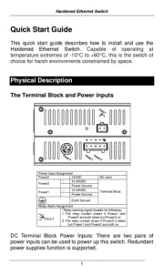
Apply Power
The switch has a 12-48VDC terminal block for power input. Only one power input
is required to operate the switch. However, redundant power supply functionality
is supported.
Note: Only use qualified power supply, either SELV, Class 2 or double insulated
per UL 60950 or UL 61010-1 or UL 61010-2-201 standards.
Device power consumption: 0.72 A
Terminal Block
The terminal block has 8 terminal posts as shown.
LED Indicators
100/1000Base-TX, 100Base-FX Interface
ON = Network connection established.
Flashing = port sending or receiving data.
ON = valid port connection at 100 Mbps.
ON = Network connection established.
Flashing = port sending or receiving data.
ON = Port connection at 1000 Mbps.
Relay Output Alarm
The switch provides relay output contacts for signaling of a user-defined power or
port failure. The relay output can be connected to an alarm signaling device.
Current is 1A at 250VAC.
Protective Earth Terminal
Power-Up Sequence
When you apply power:
All Link/ACT LEDs blink momentarily.
The Power 1 LED goes ON.
LEDs for every port connected to a device flash, as the switch conducts a Power
On Self-Test.
Console Configuration
▪ Connect to the switch console by connecting a DB-9 cable to the console
port of the switch and to the serial port of a computer running a terminal
emulation application (such as HyperTerminal or Putty).
▪ Configuration settings of the terminal-emulator: Baud rate: 115,200bps,
Data bits: 8, Parity: none, Stop bit: 1, Flow control: none.
▪ The default login name is “root,” no password.
Web Configuration
▪ Log in to the switch by launching a web browser and entering 192.168.1.10
in the address bar.
▪ Enter the default login ID: root (no password) and click “Login.” The system
information screen will display as shown below.
Other information
DIN-Rail assembly, startup, and dismantling
Assembly: Place the Switch on the DIN rail from above using the slot. Push the
front of the Switch toward the mounting surface until it audibly snaps into place.
Startup: Connect the supply voltage to start the switch via the terminal block.
Dismantling: Pull out the lower edge and then remove the Switch from the DIN
rail.
Power wiring information:
▪ Use cable type - AWG (American Wire Gauge) 18-24 and the corresponding
pin type cable terminals. Tighten terminal screws with a torque value of 1.7
lb-in. Do not use excessive force when fixing wiring.
▪ Use copper conductors only
▪ The rating of the power wire used must be at least 105°C.
Manufacturer information:
EtherWAN Systems, Inc.
33F, No. 93, Sec. 1, Xintai 5th Rd., Xizhi Dist., New Taipei City, 221 Taiwan
The full product manual can be downloaded from: