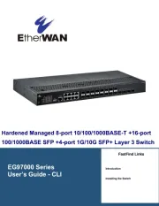
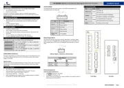
EtherWAN IG5 L Rack Manual
| Mærke: | EtherWAN |
| Kategori: | bryter |
| Model: | IG5 L Rack |
Har du brug for hjælp?
Hvis du har brug for hjælp til EtherWAN IG5 L Rack stil et spørgsmål nedenfor, og andre brugere vil svare dig
bryter EtherWAN Manualer
8 November 2025
8 November 2025
8 November 2025
7 November 2025
7 November 2025
7 November 2025
7 November 2025
6 November 2025

4 November 2025

4 November 2025
bryter Manualer
- Fantini Cosmi
- EXSYS
- Philips
- Renkforce
- Allnet
- Crestron
- Tenda
- Grässlin
- Blustream
- Mueller
- Whale
- Generac
- WyreStorm
- Mercusys
- Victron Energy
Nyeste bryter Manualer
7 November 2025
6 November 2025

3 November 2025

3 November 2025

3 November 2025
26 Oktober 2025
19 Oktober 2025
17 Oktober 2025
16 Oktober 2025
16 Oktober 2025