EXSYS EX-41052-2 Manual
EXSYS
Ikke kategoriseret
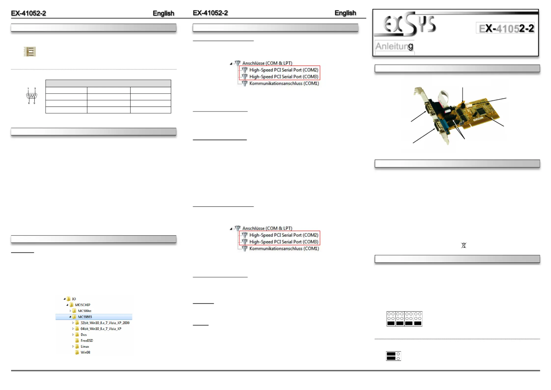
EX-41052-2
| Mærke: | EXSYS |
| Kategori: | Ikke kategoriseret |
| Model: | EX-41052-2 |
| Bredde: | 120 mm |
| Dybde: | 40 mm |
| Vægt: | 200 g |
| Produktfarve: | Grey, Yellow |
| Opbevaringstemperatur (T-T): | -40 - 75 °C |
| Relativ luftfugtighed ved drift (H-H): | 5 - 95 % |
| Driftstemperatur (T-T): | 0 - 55 °C |
| Certificering: | WHQL\r\nFCC, CE |
| Effektkrav: | 3.3V/5V |
| Bæredygtighedscertifikater: | RoHS |
| Understøttede Linux-operativsystemer: | Ja |
| Værtsgrænseflade: | PCI |
| Intern: | Ja |
| Stik: | 1 x 9 pin D-SUB |
| Understøttede operativsystemer til servere: | Windows Server 2003, Windows Server 2003 x64, Windows Server 2008, Windows Server 2008 R2, Windows Server 2008 x64 |
| Seriel grænsefladetype: | RS-232 |
| Antal serielle porte: | 2 |
| Dataoverførselshastighed: | 0.1152 Mbit/s |
| Perifere (Molex) strømstik (4-pin): | 1 |
| Output-grænseflade: | Seriel |
| Chipsæt: | MosChip MCS9865IV-AA |
Har du brug for hjælp?
Hvis du har brug for hjælp til EXSYS EX-41052-2 stil et spørgsmål nedenfor, og andre brugere vil svare dig
Ikke kategoriseret EXSYS Manualer

3 December 2025

2 December 2025

30 November 2025

28 November 2025

27 November 2025

26 November 2025
12 November 2025
12 November 2025
12 November 2025
12 November 2025
Ikke kategoriseret Manualer
- Emko
- Parasound
- Toparc
- Njoy
- Star Micronics
- Watercool
- Aqua Marina
- True Blue Power
- DigitSole
- DEXP
- Pyle
- Analog Way
- Gurari
- Sheeran Looper
- TikkTokk
Nyeste Ikke kategoriseret Manualer

17 December 2025

17 December 2025

17 December 2025

17 December 2025

17 December 2025

17 December 2025

17 December 2025

17 December 2025

17 December 2025

17 December 2025