EXSYS EX-41388 Manual
EXSYS
Ikke kategoriseret
EX-41388
| Mærke: | EXSYS |
| Kategori: | Ikke kategoriseret |
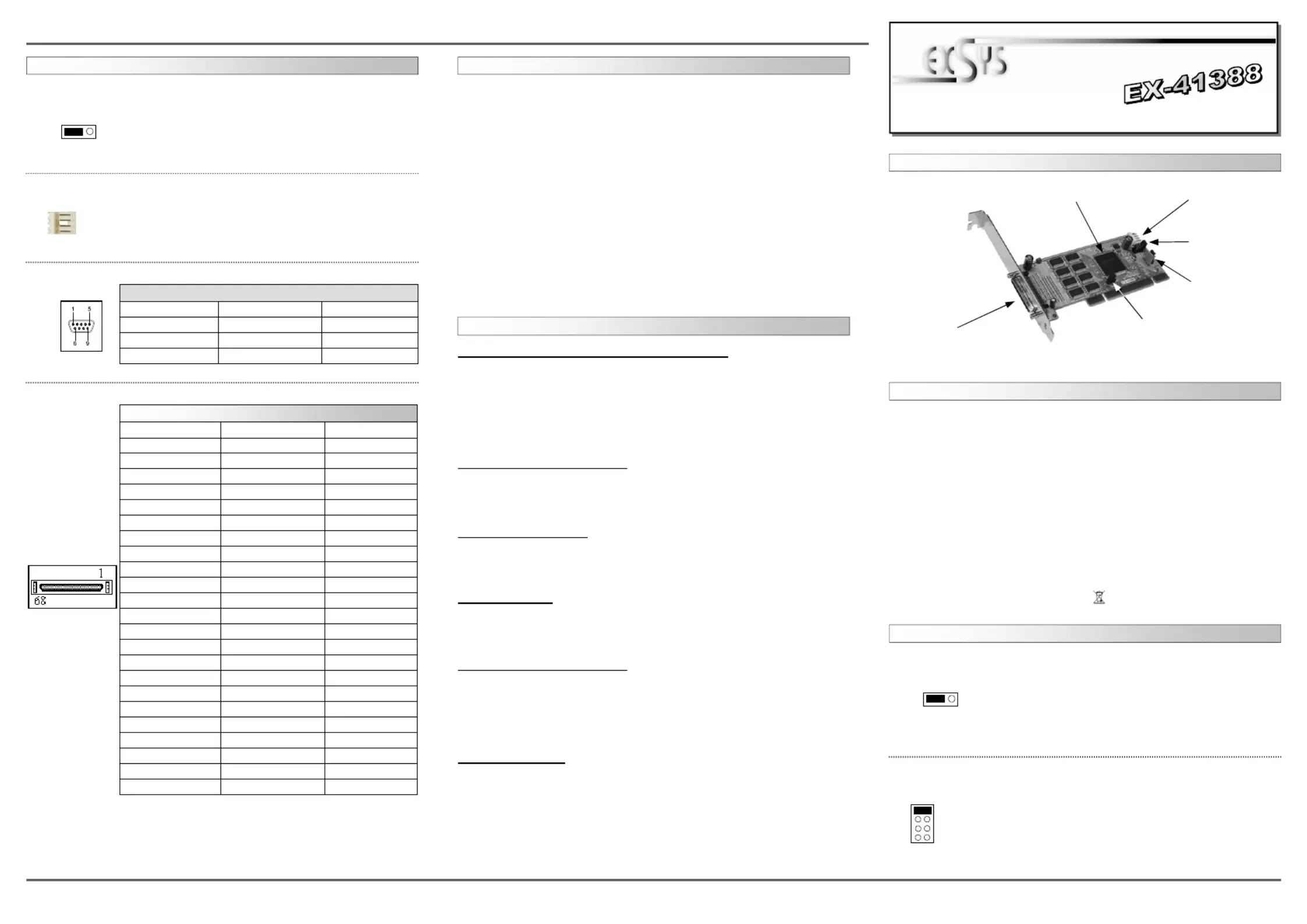
| Model: | EX-41388 |
| Bredde: | 120 mm |
| Dybde: | 61 mm |
| Vægt: | 700 g |
| Brugervejledning: | Ja |
| Opbevaringstemperatur (T-T): | -40 - 75 °C |
| Relativ luftfugtighed ved drift (H-H): | 5 - 95 % |
| Driftstemperatur (T-T): | 0 - 55 °C |
| Kabler inkluderet: | Seriel |
| Forbindelsesteknologi: | Ledningsført |
| Certificering: | CE, FCC |
| Mac kompabilitet: | Ingen |
| Bæredygtighedscertifikater: | RoHS |
| Understøttede Windows-operativsystemer: | Ja |
| Understøttede Linux-operativsystemer: | Ja |
| Værtsgrænseflade: | PCI |
| Intern: | Ja |
| Seriel grænsefladetype: | RS-232 |
| Antal serielle porte: | 8 |
| Output-grænseflade: | Seriel |
| Chipsæt: | SystemBase 16C1058PCI |
Har du brug for hjælp?
Hvis du har brug for hjælp til EXSYS EX-41388 stil et spørgsmål nedenfor, og andre brugere vil svare dig
Ikke kategoriseret EXSYS Manualer

3 December 2025

2 December 2025

30 November 2025

28 November 2025

27 November 2025

26 November 2025
12 November 2025
12 November 2025
12 November 2025
12 November 2025
Ikke kategoriseret Manualer
- DK2 Power
- Master Lock
- Airman
- On-Q
- Avenview
- Kessler
- Dahle
- Cookut
- GoldenEar
- ViewZ
- PETECHTOOL
- Colt
- SE Electronics
- Ibm
- Nordic Winter
Nyeste Ikke kategoriseret Manualer

17 December 2025

17 December 2025

17 December 2025

17 December 2025

17 December 2025

17 December 2025

17 December 2025

17 December 2025

17 December 2025

17 December 2025