EXSYS EX-44342 Manual
EXSYS
Ikke kategoriseret
EX-44342
| Mærke: | EXSYS |
| Kategori: | Ikke kategoriseret |
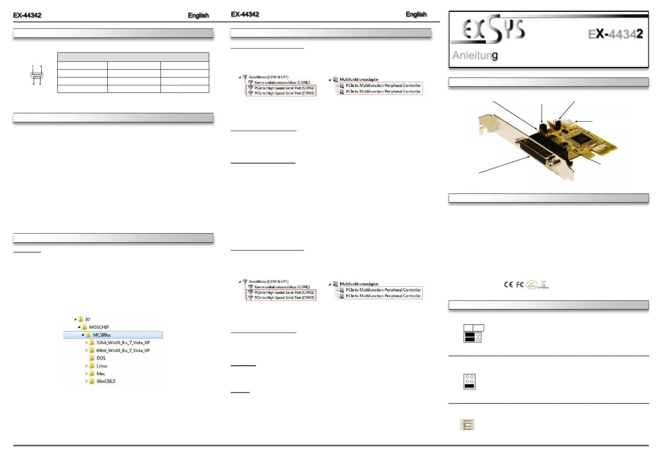
| Model: | EX-44342 |
| Bredde: | 66 mm |
| Dybde: | 65 mm |
| Understøttede Windows-operativsystemer: | Ja |
| Understøttede Mac-operativsystemer: | Ja |
| Understøttede Linux-operativsystemer: | Ja |
| Værtsgrænseflade: | PCIe |
| Intern: | Ja |
| Plug and play: | Ja |
| Seriel grænsefladetype: | RS-232 |
| Data-bits: | 5, 6,7, 8 |
| Stop bits: | 1, 1.5, 2 |
| Output-grænseflade: | Seriel |
Har du brug for hjælp?
Hvis du har brug for hjælp til EXSYS EX-44342 stil et spørgsmål nedenfor, og andre brugere vil svare dig
Ikke kategoriseret EXSYS Manualer

3 December 2025

2 December 2025

30 November 2025

28 November 2025

27 November 2025

26 November 2025
12 November 2025
12 November 2025
12 November 2025
12 November 2025
Ikke kategoriseret Manualer
- V7
- Hario
- Ozone
- Mahlkönig
- Prowise
- Metro
- AMX
- Ear Labs
- Skymaster
- Primacoustic
- Cooper & Quint
- Maxsa
- APsystems
- Anywhere Cart
- Carcomm
Nyeste Ikke kategoriseret Manualer

17 December 2025

17 December 2025

17 December 2025

17 December 2025

17 December 2025

17 December 2025

17 December 2025

17 December 2025

17 December 2025

17 December 2025