EXSYS EX-44388 Manual
EXSYS
Ikke kategoriseret
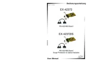
EX-44388

| Mærke: | EXSYS |
| Kategori: | Ikke kategoriseret |
| Model: | EX-44388 |
| Bredde: | 89 mm |
| Dybde: | 75 mm |
| Vægt: | 1000 g |
| Brugervejledning: | Ja |
| Opbevaringstemperatur (T-T): | -40 - 75 °C |
| Driftstemperatur (T-T): | 0 - 55 °C |
| Understøttede Windows-operativsystemer: | Ja |
| Værtsgrænseflade: | PCIe |
| Intern: | Ja |
| Drivere inkluderet: | Ja |
| Data-bits: | 5, 6,7, 8 |
| Stop bits: | 1, 1.5, 2 |
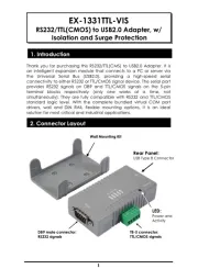
| Output-grænseflade: | Seriel |
| Udvidelseskort formfaktor: | Lavprofil |
Har du brug for hjælp?
Hvis du har brug for hjælp til EXSYS EX-44388 stil et spørgsmål nedenfor, og andre brugere vil svare dig
Ikke kategoriseret EXSYS Manualer

3 December 2025

2 December 2025

30 November 2025

28 November 2025

27 November 2025

26 November 2025
12 November 2025
12 November 2025
12 November 2025
12 November 2025
Ikke kategoriseret Manualer
- Sensiplast
- Contour Design
- SmartAVI
- Tiger
- SurgeX
- Homak
- Fisher & Paykel
- Hacienda
- SetonixSynth
- Yaesu
- Minuteman
- Vigitron
- NordicTrack
- Silver Style
- Omnilux
Nyeste Ikke kategoriseret Manualer

17 December 2025

17 December 2025

17 December 2025

17 December 2025

17 December 2025

17 December 2025

17 December 2025

17 December 2025

17 December 2025

17 December 2025