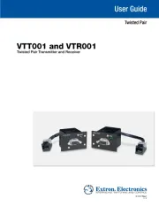
Extron VTT001 Manual
Læs gratis den danske manual til Extron VTT001 (1 sider) i kategorien AV forlænger. Denne vejledning er vurderet som hjælpsom af 5 personer og har en gennemsnitlig bedømmelse på 5.0 stjerner ud af 3 anmeldelser.
Har du et spørgsmål om Extron VTT001, eller vil du spørge andre brugere om produktet?
Produkt Specifikationer
| Mærke: | Extron |
| Kategori: | AV forlænger |
| Model: | VTT001 |
| Type: | AV sender |
| Vekselstrømsindgangsspænding: | 100-240 V |
| Vekselstrømsindgangsfrekvens: | 50 - 60 Hz |
| Vægt: | 500 g |
| Produktfarve: | Sort |
| Opbevaringstemperatur (T-T): | -40 - 70 °C |
| Relativ luftfugtighed ved drift (H-H): | 10 - 90 % |
| Relativ luftfugtighed ved opbevaring (H-H): | 10 - 90 % |
| Driftstemperatur (T-T): | 0 - 50 °C |
| Maksimal opløsning: | 1600 x 1200 pixel |
| Dimensioner (BxDxH): | 35 x 35 x 35 mm |
| Impedens: | 75 ohm (Ω) |
| LED-indikatorer: | Ja |
| VGA (D-Sub) indgangsporte: | 1 |
| Understøttede kabeltyper: | Cat5, Cat5e, Cat6 |
Har du brug for hjælp?
Hvis du har brug for hjælp til Extron VTT001 stil et spørgsmål nedenfor, og andre brugere vil svare dig
AV forlænger Extron Manualer
AV forlænger Manualer
- WyreStorm
- Lindy
- ASSMANN Electronic
- Aitech
- TechLogix Networx
- PureTools
- Liberty
- Micro Connect
- Marshall Electronics
- Polycom
- Kopul
- Adder
- Tripp Lite
- Vivotek
- Renkforce
Nyeste AV forlænger Manualer