To get access to the parameter configuration menu, press button ■ + for 5 seconds.
or select the parameter to be modified.
pressed, use button to set the desired value. or
is released, the newly programmed value is stored and the following parameter is displayed.
To exit from the setup, press button ■
Readout scale (see table of input specifications)
Caution: upon changing the value, it is then absolutely necessary to the param-SCL reconfigure
eters relevant to the absolute and relative temperatures ( , , , etc..)SPL SPH 1SP 1HY
-50°...SPH Minimum limit for setting1SP
SPL...150° Maximum limit for setting.1SP
SPL... SPH Setpoint (value to be maintained in the room).
With =H you select control with hysteresis: parameters , are used.1CM Y1HY 1T0 1T1 and
With =PID you select a Proportional-Integral-Derivative control mode: parameters , , 1CM 1PB 1IT
1DT 1AR 1CT, , will be used
REF; HEA Refrigerating (REF) or Heating (HEA) control mode.
0...19.9° OFF/ON thermostat di ferential. With =0 the output is always of 1HY ff.
0...30min Minimum o f time.f
After output been turned f, it remains inactive minutes 1 has of for 1T0 regardless of the
temperature value measured.
0...30min Minimum on time. ( ).the following parameter will be 1PF
After output 1 has been turned on, it remains active for 1T1 minutes regardless of the temperature
0...19.9° Proportional bandwidth.
Temperature takes by changing control place the
ON of the the closer the time output: temperature
to the the less of setpoint, time activation. A small
proportional band increases the promptness of
response of the to system temperature variations,
but make it stable. A tends to less purely
proportional stabilises temperature control the
within proportional band but the does not cancel
the deviation from setpoint.
With =0 the output is always o1PB ff.
0...999s Integral action time.
The error cancelled an steady-state is by inserting
integral action. integral action time, determines The
the speed the with which steady-state temperature
is achieved, but high ( low) may be a speed 1IT the
cause overshoot instability in of and the response.
With =0 the integral control is disabled.1IT
0...999s Derivative action time.
Response overshoot may be reduced
a derivative Action. A high derivative action (1DT
high) makes system very sensitive the to small
temperature variation causes instability s and . With
1DT=0 the derivative control is disabled.
0...100% Reset of integral action time referred to 1PB
Decreasing reduces integral action zone, consequently the parameter 1AR the control and the
overshoot (see figure on paragraph ).1IT
It’s the the ON changes. The the to controlled period in which output time quicker system be
reacts to the smaller the order to temperature variations, cycle time must be, in obtain higher
temperature stability and less sensitivity to load variations.
ON/OFF Output state in case of probe failure.
NON : output disabled (always o f). (fthe next parameter will be ATM)
THR: output programmed for second thermostat control ( ).the next parameter will be 2SM
AL0: contacts open when an alarm condition occurs (the next parameter will be ATM).
AL1: contacts make when an alarm condition occurs (the next parameter will be ATM).
Channel 2 set nt ma e a solpoi y b b u (te 2SM=ABS), or a d fferenti ial relat e to setiv poi (nt 1 2SM=REL)
SPL...SPH Auxiliary output switchover temperature ( )the next parameter will be 2CH
-19.9...19.9° Temperature di ferential relative to The auxiliary output setpoint is equal to f1SP. 1SP 2DF+
ON/OFF refrigerating control
ON/OFF control in refrigeration
ON/OFF control in heating
ON/OFF control in refrigeration. Setpoint 2
relative to setpoint 1 ( =THR, =REF)OAU 2CH
ON/OFF control in heating. Setpoint 2
relative to setpoint 1 ( =THR, =HEA)OAU 2CH
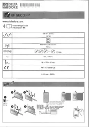
12Vac/dc ±10%, 2W (L02AI-/L02CI-/L02DI-)
110 - 230 ac±10%, 50/60Hz, 3W (L02AM-/L02CM-/L02DM-)V
see table of input specifications
see table of input specifications
see table of input specifications
-10 … +50°C; 15%...80% U.R.
EN55022 (Class B); EN50082-1
REF; HEA Refrigerating control (REF) or heating control mode (HEA) for the auxiliary output.
0...19.9° Di ferential of thermostat 2. With =0 the auxiliary output always remains of2HY ff.
0...30min Minimum o f time.f
After output 2 has been turned of f, it remains inactive for 2T0 minutes regardless of the temperature
0...30min Minimum on time.
After output 2 has been turned on, it remains active for 2T1 regardless of the minutes temperature
ON/OFF Auxiliary output state in case of probe failure.
Alarm threshold management.
NON all temperat: ure alarms are inhibi (ted the following parameter will be SB).
ABS: the values programmed n iALA and represent the real alarm thresholds.AHA
REL: the values programmed in ALR and AHR are alarm differentials referred to 1SP and 1SP+1HY.
-50°...AHA Low temperature alarm threshold.
ALA...150° High temperature alarm threshold.
-12.0...0° Low temperature alarm di ferential. f
With =0 the low temperature alarm is excludedALR
0...12.0° High temperature alarm di ferential. f
With =0 the high temperature alarm is excludedAHR
0...120min Delay before alarm temperature warning.
NO/YES Stand-by button enabling.
Sensor input selection (see table of input specifications).
WARNING: “0mA/4mA”, and “T2” are not available
In the models L02A--/L02D-- only.
-19.9...RHI Minimum range value (function not available)
RLO takes the minimum value measured by the transmitter (i.e. the value matching 0V, 0/4mA).
RLO...99.9 Maximum range value (function not available)
RHI takes the maximum value measured by the transmitter (i.e. the value matching 1V, 20mA)
-12.5...12.5° T1 offset.Probe
1...30min Delay for minimum temperature (TLO) and maximum temperature (THI) logging.
1...255 address for PC communication (function not available)
Temperature alarm with relative thresholds,
refrigerating control (ATM 1CH=REL, =REF)
Temperature alarm with relative thresholds,
heating control (ATM 1CH=REL, =HEA).
During normal operation, the display shows either the temperature measured or one of the following indications:
Probe T1 overrange or failure
In tuning: timeout1 error
Room high temperature alarm
In tuning: timeout2 error
Room low temperature alarm
In tuning: overrange error
The information available in this menu is:
Maximum temperature recorded
Minimum temperature recorded
Access to menu and information displayed.
Press and immediately release button ■
or select the data to be displayed.
To exit from the menu, press button ■
Reset of THI, TLO recordings
or select the data to be reset.
Display the value with button ■
CHANNEL 1 SETPOINT (display and modification of desired temperature value)
Press and release button ■
: the ED L L bli1 nks, the d spla shoi y ws 1 P for 1 second and then the set nt assocS poi iated value.
or to set the desire valud e (adjustment s i within the minimum SPL and maximum SPH limit .)
To store the new value press button ■
, or wait for 10 seconds.
To go back to normal mode without saving the new value, press ■
With auxiliary output ( the set as thermostat control ■ =THR), itOAU ’s to 2 the normal possible modify setpoint during operation
Press and release button ■
: LED L2 blinks, display shows 2S if setpoint is absolute the the P for 1 second 2 an threshold
( =ABS), alternatively display shows2SM the 2DF, if setpoint is relative setpoint ( =REL), value 2 a threshold to 1 2SM then the
associated to the parameter appears.
or to set the desired value.
To store the new value press button ■
To go back to normal mode without saving the new value, press ■
Button , when pressed for 3 seconds, allows the controller to e pb ut on a standby or output control to be resumed (with SB=YES only).
The attempted the controllers keypad lock avoids undesired, potentially dangerous operations, which might be when is operating
in public menu, =YES inhibit functions buttons. a place. In the INFO set parameter LOC to all of the To normal resume operation
of keypad, adjust setting so that LOC=NO.
CONTROLLER AUTOTUNING IN PID MODE
In the mode set =PID; that matches the mode setup (see configuration parameters): 1CM make sure 1CH desired operation
( =REF for refrigerating control, =HEA for heating control); then adjust setpoint at the desired value.1CH 1CH 1SP
During operation, keep buttons normal
+ pressed for seconds. 1CT on the 3 blinks display. + or set the With cycle
time in define dynamic be order to the of the process to controlled. To the press abort autotuning function,
+ or wait for 30 seconds.
During entire autotuning phase, display TUN with actual temperature measured. power failure, the the alternates the In case of
when power is resumed, initial autotest phase, resumes autotuning function. after the the controller the To the abort autotuning,
without modifying previous parameters, keep button the control
pressed for seconds. the has place 3 After autotuning taken
successfully, the controller updates the control parameters and start to control.
If the autotuning function failed, the display shows an error code:
E1 the controller not the the Increase timeout1 error: could bring temperature within proportional band.■ in heating 1SP case of
control, vice versa, decrease in case of refrigerating control and re-start the process.1SP
E2 the has not ended the Re-start the timeout2 error: autotuning within maximum time allowed (1000 cycle times). autotuning ■
process and set a longer cycle time 1CT.
E3 temperature overrange: check was caused by probe malfunction, that the error not a then decrease ■ in heating 1SP case of
control, vice versa increase in case of refrigerating control and then re-start the proce1SP ss.
To eliminate the error indication and return to the normal mode, press button ■
To reduce overshoot, reduce the integral action reset ■1AR
To increase the response speed of the system, reduce the proportiona banl d ■1PB. Ca tu ion: doin g this makes the system less stable.
To reduce swings in steady-state temperature, increase the integral action time ■ system stability1IT; is thus increased, although
its response speed is decreased.
To the speed of response to the the increase variations in temperature, increase derivative action time ■ Caution: high 1DT. a
value makes the system sensitive to small variations and it may be a source of instability.
Have a precision reference thermometer or a calibrator to hand. Ensure that ■ =0 and =0.OS1 SIM
Switch the controller o f then on again.f ■
During the auto-test phase, press buttons ■
0AD+ and keep them pressed till the controller shows .
and select or a of a constant the scale 0AD SAD 0AD: allows calibration 0, inserting correction over whole
of a of the top part of the scale a the measurement. SAD allows calibration measurement with proportional correction between
to the and then + or to the read the the display value use make value coincide with value measured by
Exit from calibration by pressing button ■
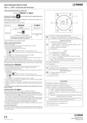
Insert the controller through a hole measuring 71x29 mm; ■
Make sure electrical connections comply with “wiring diagrams”. that the paragraph To the effects of reduce electromagnetic ■
disturbance, keep the sensor and signal cables well separate from the power wires.
Fix the controller to the panel means of the by suitable clips, by pressingly gently; if fitted, check that the adheres rubber gasket■
to the panel perfectly, in order to prevent debris and moisture infiltration to the back of the instrument.
Place the probe T1 inside the room in a point that truly represents the temperature of the stored product. ■
Channel 1 setpoint modification
Channel 2 setpoint modification
Modify Setpoint 1 / Decrease button
Increase / Modify Setpoint 2 button
Thank you for having chosen a Fantini Cosmi product. Before installing the instrument, please read these instructions carefully
to ensure maximum performance and safety.
115... ~ (L02DM-) o 12Vac/dc (L02DI-)230V
115... ~ (L02CM-) o 12Vac/dc (L02CI-)230V
115... ~ (L02AM2) o 12Vac/dc (L02AI2B)230V
RANGE [MEASUREMENT ACCURACY]
INP=T1 ---TC “J” 0÷450°C [ < ±3°C ]
[<±0.3°C (-40÷130°),±1°C]
[<±0.6°F (-40÷221°),±2°F]
[<±0.3°C(-40÷100°), ±1°C]
[<±0.3°C (-40÷100°),±1°C]
[<±0.6°F (-40÷210°),±2°F]
(L02AI2B/L02CI2B/L02DI2B)
(L02AM2/L02CI1B/L02CM-/L02DI1B/L02DM-)
20090 Caleppio di Settala, Milano, ITALY
Ph. +39 02 956821 | Fax +39 02 95307006