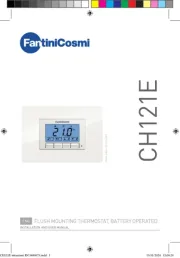
Thank you for having chosen a Fantini Cosmi product. Before installing the instrument, please read these instructions carefully
to ensure maximum performance and safety.
.nottub tniopteS Increase button.
.nottub esaerceD Exit / Stand-by button.
Insert the controller through a hole measuring 71x29 mm.
Make sure that electrical connections comply with the paragraph “wiring diagrams”. To reduce the eects of electromagnetic
disturbance, keep the sensor and signal cables well separate from the power wires.
Fix the controller to the panel by means of the suitable clips, by pressingly gently; if fi
tted, check that the rubber gasket
adheres to the panel perfectly, in order to prevent debris and moisture infi
ltration to the back of the instrument.
Place the probe T1 inside the room in a point that truly represents the temperature of the stored product.
During normal operation, the display shows either the temperature measured or one of the following indications:
In tuning: timeout1 error
Probe T1 overrange or failure
In tuning: timeout2 error
In tuning: overrange error
SETPOINT (display and modifi
cation of desired temperature value)
for at least half second, to display the setpoint value.
to set the desired value (adjustment is within the minimum
is released, the new value is stored.
, when pressed for 3 seconds, allows the controller to be put on a standby or output control to be resumed (with
CONTROLLER AUTOTUNING IN PID MODE
value matches the desired control mode (
1PB 1PB<0 for heating; >0 for refrigeration).
1CT blinks on the display.
set the cycle time in order to defi
ne the dynamic of the process to be controlled.
To start autotuning press
or wait for 30 seconds. To abort the autotuning function, press
During the entire autotuning phase, the display alternates
with the actual temperature measured.
In case of power failure, when power is resumed, after the initial autotest phase, the controller resumes the autotuning
To abort the autotuning, without modifying the previous control parameters, keep button
After the autotuning has taken place successfully, the controller updates the control parameters and start to control.
If the autotuning function failed, the display shows an error code:
E1 timeout1 error: the controller could not bring the temperature within the proportional band. Increase
heating control, vice versa, decrease
1SP in case of refrigerating control and re-start the process.
E2 timeout2 error: the autotuning has not ended within the maximum time allowed (1000 cycle times). Re-start the autotuning
process and set a longer cycle time
E3 temperature overrange: check that the error was not caused by a probe malfunction, then decrease
control, vice versa increase
1SP in case of refrigerating control and then re-start the process.
To eliminate the error indication and return to the normal mode, press button
To reduce overshoot, reduce the integral action reset
To increase the response speed of the system, reduce the proportional band
1PB . Caution: doing this makes the system less
To reduce swings in steady-state temperature, increase the integral action time
1IT ; system stability is thus increased,
although its response speed is decreased.
To increase the speed of response to the variations in temperature, increase the derivative action time
value makes the system sensitive to small variations and it may be a source of instability.
Have a precision reference thermometer or a calibrator to hand.
Switch the controller o then on again.
During the auto-test phase, press buttons
, and keep them pressed till the controller shows
select or : allows a calibration of 0, inserting a constant correction over the whole 0AD SAD 0AD
allows a calibration of the top part of the measurement scale with a proportional correction
between the calibration point and 0.
to display the value and then use
to make the read value coincide with the value measured by the
Exit from calibration by pressing button
Setup menu is accessed by pressing buttons
select the parameter to be modified.
to set the desired value.
is released, the newly programmed value is stored and the following parameter is displayed.
To exit from the setup, press button
L02B-- rof C°501/9.99 … 9.91-/04-
L22E-- rof .H.r% 100 … 0.0
2°C : measuring range -40 … 105°C for L02B--
°F : measuring range -40 … 221°F for L02B--
Caution: upon changing the SCL value, it is then absolutely necessary to re-congure the parameters relevant to the
absolute and relative temperatures (
SPL SPH 1SP, , , 1HY, etc..).
-50..SPH Minimum limit for
SPL.150° Maximum limit for
SPL... SPH Setpoint (value to be maintained in the room).
=HY you select control with hysteresis: parameters
=PID you select a Proportional-Integral-Derivative control mode: parameters
1PB, 1IT, 1DT, 1AR, 1CT will
-19.9…19.9°C Thermostat dierential [control with hysteresis].
on a value greater than zero to make the output work in refrigerating mode, vice versa set on a value lower
than zero to make the output work in heating mode. With
1HY=0 the output is always o.
Fig. 1a. ON/OFF refrigerating control (
>0) Fig. 1b. ON/OFF heating control (
-19.9…19.9°C Proportional band [PID control].
on a value greater than zero to make the output work
in refrigerating mode, vice versa set on a value lower than
zero to make the output work in heating mode. With
With a proportional controller, the temperature is controlled
by varying the time of activation of the output. The nearer the
temperature to set point, the less time of activation. A small
proportional band increases the promptness of response
of the system to temperature variations, but tends to make
it less stable. A purely proportional control stabilises the
temperature within the proportional band but does not cancel
the deviation from the set point.
0…999s Integral action time [PID control].
rror is cancelled by inserting an
integral action into the control system. The integral action
time, determines the speed with which the steady-state
temperature is achieved, but a high speed (
the cause of overshoot and instability in the response. With
1IT=0 the integral control is disabled.
0…999s Derivative action time [PID control].
Response overshoot in a system controlled by a Proportional-
Derivative controller may be reduced by inserting a derivative
action in the control. A high derivative action (1
makes the system very sensitive to small temperature
variations and causes instability. With 1DT= 0 the derivative
0…100% Reset of integral action time referred to
Decreasing the parameter 1AR
reduces the integral control action zone, and consequently the overshoot (see gure
=HY), after the output has switched on or o, it will remain in the new state for a minimum
time of 1CT seconds, regardless of the temperature value.
=PID), the cycle time is the period of time in which the output completes a cycle (Time ON +
Time OFF). The faster the system to be controlled reacts to temperature changes, the smaller the cycle time should
be, in order to obtain a greater temperature stability and less sensitivity to load variations.
ON / OFF Output state in case of probe failure.
NON / SBY With BAU =SBY, the stand-by button is enabled.
0...100 Display slowdown.
-12.5..12.5°C Probe T1 oset.
1...255 address for PC communication. (function not available)
L22E…: <±0.7%r.H. in the measuring range
L02B…: <±0.3°C -40…100°C; ±1°C out of that range
Temperature
Temperature
Temperature
230V~ (L22EM1A) / 12Vac/dc (L22EI1A)
230V~ (L02BM1A) / 12Vac/dc (L02BI1A)
L02BI1A/L22EI1A 12Vac/dc±10%, 3W
L02BM1A/L22EM1A 230Vac±10%, 50/60Hz, 3W
L02B... L22E
20090 Caleppio di Settala, Milano, ITALY
Ph. +39 02 956821 | Fax +39 02 95307006