Gira System 106 Manual
Gira
Intercomsystem
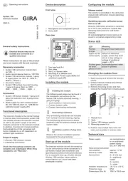
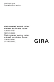
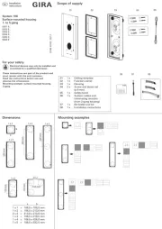
System 106

| Mærke: | Gira |
| Kategori: | Intercomsystem |
| Model: | System 106 |
| Kode for international beskyttelse (IP): | IP54 |
| Bredde: | 106.5 mm |
| Højde: | 106.5 mm |
| Produktfarve: | Rustfrit stål |
| Driftstemperatur (T-T): | -25 - 70 °C |
| Husmateriale: | Rustfrit stål |
| Forbindelsesteknologi: | Ledningsført |
| Højttalertelefon: | Ja |
| Tastaturbelysning: | Ja |
| Antal knapper: | 1 |
| Strøm over Ethernet (PoE): | Ingen |
| Stiktype: | 10-polet stik |
| Indendørsenhed inkluderet: | Ingen |
| Udendørsenhed inkluderet: | Ja |
| Moduler, antal (maks.): | 1 modul(er) |
| Strømtype for udendørsenhed: | Vekselstrøm/jævnstrøm |
Har du brug for hjælp?
Hvis du har brug for hjælp til Gira System 106 stil et spørgsmål nedenfor, og andre brugere vil svare dig
Intercomsystem Gira Manualer
20 September 2024

9 August 2024

5 August 2024
2 August 2024
1 August 2024
1 August 2024
30 Juli 2024
30 Juli 2024
26 Juli 2024
22 Juli 2024
Intercomsystem Manualer
- Nortek
- Hikvision
- TCS
- Chamberlain
- Busch-Jaeger
- Akuvox
- WHD
- Viking
- GEV
- Vimar
- Toucan
- Midland
- Emos
- Hanwha
- Foscam
Nyeste Intercomsystem Manualer

28 Marts 2025
27 Marts 2025
27 Marts 2025
27 Marts 2025
10 Marts 2025
20 Februar 2025
20 Februar 2025
20 Februar 2025
20 Februar 2025

5 Februar 2025