TB6980/TB7980 62-0238 400-150-005-B 3/23/06 1/6
The TB6980/TB7980 digital thermostats provide proportional plus
integral individual space temperature control in zoned commercial
HVAC systems such as hydronic and pressure dependent VAV with
or without reheat. There are four different models:
Depending on the model, the thermostat can have up to three out-
puts that can be used for the following applications:
Floating or Modulating damper/valve actuator control
Damper/valve actuator control with duct reheat and auxiliary
heat (B models only)
Hydronic systems (room control, perimeter heating and cool-
ing)
Accessories
R841 family of electromechanical relays
T7770A3002 remote room sensor
50014156-002 remote room sensor
32004800-001 bare thermistor
50014157-001 duct temperature sensor
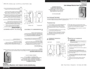
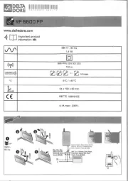
nRemove the thermostat from its base by unscrewing the cap-
tive screw and tilting the bottom of the thermostat up. The
screw cannot be completely removed.
oPass the wires through the center hole of the base and secure
the base to the wall or onto an electrical box.
pWire the thermostat. See section 2.2 for terminal designations
and section 3 for typical wiring diagrams.
qReinstall the thermostat onto its base and secure with the cap-
tive screw.
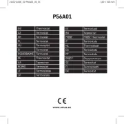
The designations of the terminals vary according to the particular
model of thermostat. Refer to the following table for the description
of each terminal.
• TB7980A (single output, modulating) • TB6980A (single output, floating)
• TB7980B (multiple output modulating) • TB6980B (multiple output, floating)
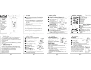
Configuration and status display
Heating mode
Temperature display
Output power display
Temperature
adjustment
button
Cooling mode
Override button
TERMINAL DESCRIPTION
1
2
24 VAC
COM Power supply
3
4
AN1
COM Output 1
TB7980 models
3
4
OPEN
CLOSED TB6980 models
5
6
T2/AN2
T2/COM Output 2 (TB6980B and TB7980B models)
7
8
T3
T3 Output 3 (TB6980B and TB7980B models)
9
10
COM
SENSOR
External sensor input. (For applications requiring
an external sensor, see section 4.2.)
9
11
COM
C-Over
Mode Changeover input (N.O. contact). See sec-
tion 5.4.2.
9
12
COM
NSB
Night Setback activation input (N.O. contact).
See section 5.5.
Note: To configure the terminals, see section 4.