JUNG 4008 TSM Manual


Læs gratis den danske manual til JUNG 4008 TSM (8 sider) i kategorien Ikke kategoriseret. Denne vejledning er vurderet som hjælpsom af 2 personer og har en gennemsnitlig bedømmelse på 4.1 stjerner ud af 1.5 anmeldelser. Har du et spørgsmål om JUNG 4008 TSM, eller vil du spørge andre brugere om produktet?

Side 1/8
Page 1
0024015020 12.10.2012
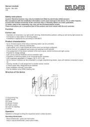
Push-button sensor module
Ref.-no.: 4008 TSM
Safety instructions
Caution! Electrical devices may only be installed and tted by electrically skilled persons.
Non-compliance with the installation information could cause damage to the device, re or other hazards.
Connect the push-button sensor module exclusively to the universal relay or dimming station (no mains potential!).
These instructions are a component part of the product and must remain with the end customer.
Correct use
Operation of consumers, e.g. light on/off, dimming, blinds/shutters up/down, calling up and saving light scenes etc.
Connection to relay station or dimming station
Installation in appliance box according to DIN 49073
Product characteristics
8 channels of the relay and dimming station can be controlled: switching, contact, dimming, blind/shutter.
16 channels for stations connected in parallel in conjunction with the push-button sensor expansion module.
All channels of the stations can be connected in the state as delivered.
Central function: all selected channels of the stations are controlled centrally
Light scenes: up to 4 light scenes can be freely congured.
Buttons can be congured corresponding to the cover kit.
Programming without additional aids
Free assignment of the buttons to the channels
Red LED as status indicator (can be switched off)
Blue orientation light (can be switched off)
Feedback of switching states on all connected push-button sensor modules and sensor modules
Up to 4 push-button sensor modules with up to 4 push-button sensor expansion modules can be connected to a single relay station (appli-
cation e.g. in two-way circuits or cross connections)
Cloning of push-button sensor modules: transmitting the button assignment of a push-button sensor module to other push-button sensor
modules (application e.g. in changeover or cross connections)
Push-button sensor modules and push-button sensor modules with expansion module can be cloned
Easy installation using 2-wire cable
Covers can be labelled using the laser labelling tool on the Internet under www.jung-lasern.de
Operation
Each button can be operated over its entire surface or top/bottom, depending on the programming. The function depends on the setting of
the station.
Switching / momentary contact: press button briey.
Move blind/shutter: press and hold button.
Stop or adjust blind/shutter: press button briey
Dimming: press and hold button
Structure of the device
Bild 1: Installation
(1) Supporting ring
(2) Frame
(3) Adapter frame
(4) Push-button sensor module
(5) Locking screw
(6) Button set
(7) Connecting terminal
(8) Box screws
Page 2
0024015020 12.10.2012
Information for electrically skilled persons
Installation and electrical connection
DANGER!
Electric shock from touching live parts in the installation environment.
An electric shock can be fatal.
Before working on the device, disconnect the power and cover live parts in the area!
Snapping on the adapter frame
An adapter frame is required depending on the switch range.
The adapter frame for the series LS is pre-mounted.
Snap adapter frame (3) in the right orientation from the front onto the module (8) (Figure 2). Observe the label „TOP“.
Connection
Attention!
Connect the push-button sensor module exclusively to the universal stations.
Installing and connecting the device
(8)
(13)
(4)
(5)
(5)
(11)
(12)
(8)
(10)
(9)
Bild 2: Installation with expansion module
(9) Connecting cable TSEM
(10) Plug-in position
(11) Push-button sensor expansion module
(12) Frame
(13) Double supporting ring
Supporting ring side A for A range, CD range
and at design.
Supporting ring side B for LS range.
When using the push-button sensor expansion module (Figure 2): vertical installation is preferred. Use the double supporting ring (13). For
installation to a ush-mounted box only, countersink the lower screws in the wall, e.g. with bore ø 6 x 10 mm. Use supporting ring as template.
DANGER!
When installing with 230 V devices under a common cover, e.g. socket outlets, there is a danger of electric shock in the event
of an error!
An electric shock can be fatal.
Do not install any 230 V devices in combination with a push-button sensor expansion module under a common cover!
Install supporting ring (1) or (13) in the right orientation on an appliance box. Observe the label „TOP“; label A or B forwards.
Use only the supplied box screws (8).
Insert frame (2) onto the supporting ring.
Preferred installation position of push-button sensor expansion module (15) is below.
Guide connecting cable (16) between supporting ring and intermediate web.
Push-button sensor expansion module: insert connecting cable (16) in the right orientation in the plug-in position (17) in the push-button
sensor module.
Do not pinch the connecting cable.
Connect push-button sensor module (4) with connecting terminal (7) to the station and insert onto the supporting ring.
Fasten the push-button sensor module(s) to the supporting ring using the enclosed plastic screws (5).
Only tighten the plastic screws lightly.


Produkt Specifikationer

Mærke: JUNG
Kategori: Ikke kategoriseret
Model: 4008 TSM

Har du brug for hjælp?

Hvis du har brug for hjælp til JUNG 4008 TSM stil et spørgsmål nedenfor, og andre brugere vil svare dig


Ikke kategoriseret JUNG Manualer
JUNG

JUNG AL2212 Manual

16 Juli 2025
JUNG

JUNG 1708IE Manual

16 Juli 2025
JUNG

JUNG FMGCR1700 Manual

16 Juli 2025
JUNG

JUNG 1731JE Manual

16 Juli 2025
JUNG

JUNG 2076-2T Manual

16 Juli 2025
JUNG

JUNG 4008 TSM Manual

16 Juli 2025
JUNG

JUNG ME2539 Manual

16 Juli 2025
JUNG

JUNG 1720NE Manual

16 Juli 2025
JUNG

JUNG BTLC1521SE Manual

16 Juli 2025
JUNG

JUNG LS1750D Manual

16 Juli 2025

Ikke kategoriseret Manualer

Nyeste Ikke kategoriseret Manualer