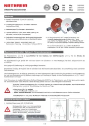
Kathrein CAS 90ro Manual


Læs gratis den danske manual til Kathrein CAS 90ro (26 sider) i kategorien Satellit antenne. Denne vejledning er vurderet som hjælpsom af 15 personer og har en gennemsnitlig bedømmelse på 4.3 stjerner ud af 8 anmeldelser. Har du et spørgsmål om Kathrein CAS 90ro, eller vil du spørge andre brugere om produktet?

Side 1/26
1 / 36
Refl ector made of aluminium, powder coated
Feed system support made of galvanised sheet steel,
powder coated
Mast clamp made of sheet steel, hot-dip galvanised
Optimal electrical data combined with very compact mecha-
nical dimensions due to o set feed
Patented tilt facility at the multi-feed adaptor plate, allows
optimisation of the LNB positions for multi-feed reception
Items supplied: Refl ector, pre-assembled mast and
feed system support, user manual
The optimum performance of the satellite antennas is only
given in conjunction with the original Kathrein LNBs.
Features
Without additional components, two universal feed systems
to receive the signals of satellites 3° or 4°
(e.g. ASTRA 19.2°/23.5°) or 6° apart (e.g. ASTRA/EUTELSAT-
HOTBIRD) can be mounted on the boom
For other satellite spacings, the multifeed adapter plates ZAS
90 (Order no: 218684) and ZAS 1218 (Order no: 204500011) are
available (see „Optional Accessories“ on page 1).
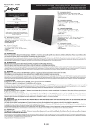
The CAS90 parabolic antenna is intended solely for the reception of satellite signals use as a domestic antenna and for only .
DIN4131 specifi es that a domestic antenna has no more than 6 m free mast length and a fi xed-end moment up to 1650Nm.
It is unsuitable for mounting on structures that are liable to vibration.
Make absolutely sure that the values for the maximum load listed in the Technical Data (on the last page) are complied with.
If this load is exceeded, parts could break away!
The CAS90 parabolic antenna is designed for use with a feed system (LNB) for reception of the signals from one satellite position, or
two feed systems for multi-feed applications for reception of the signals from two satellite positions with 3°–4° or 6° satellite spa-
cing.
When the additional ZAS 90 or ZAS 1218 multi-feed adapter plate is used, the parabolic antenna is also suitable for three feed sys-
tems. The feed systems and instructions for their installation are not included in the scope of supply of the parabolic antenna.
Do not use the parabolic antenna for purposes other than those listed in this manual! Any use other than that specifi ed
above will void the warranty or guarantee.
In particular, any of its or never modify components t any components other than those expressly intended by the
manufacturer for use with the antenna.
Breach of these rules may lead to the antenna no longer being suffi ciently stable and safe!
Intended Use
CAS 90gr 20010033
CAS 90ro 20010034
CAS 90ws 20010035
Sat Antennas
Optional Accessories
ZAS 90, order no. 218684 multi-feed adapter plate
Installation items 2 and 3 cannot be mounted
at the same time.
ZAS 1218, order no. 204500011 multi-feed adapter plate
Without notches for any satellite spacing
2 / 36
Under no circumstances install antennas in the vicinity of overhead power cables, otherwise the absolutely essen-
tial clearance requirements may no longer be satisfi ed. Maintain a clearance of at least 1 m from all other electrical
devices in all directions!
If you or metal parts of the antenna touch any electrical device there is a serious risk of a fatal electric shock!
Never work on antenna systems during a thunderstorm or when a thunderstorm is approaching.
There is a risk of a fatal electric shock!
Never install antennas on buildings with easily fl ammable roof coverings such as straw, reeds or similar materials!
Otherwise there is a risk of fi re due to atmospheric over-voltages (static charges) or lightning discharges
(e.g. during thunderstorms).
The installation operations described here assume good craftsmanship capabilities and knowledge of the behaviour
of materials under the e ects of wind. Therefore if you do not possess the required skills, have this work performed
by a specialist.
The person doing the work must wear strong non-slip footwear, must not be liable to dizziness, must be able to
move around safely on the roof and have a secure standing and attachment position (if necessary, wear a safety
harness when on the roof).
Make sure that the roof is able to bear your weight. Never walk on fragile or unstable surfaces! In case of doubt,
contact a qualifi ed specialist dealer or specialist roo ng contractor to nd an appropriate installation location.
Do not go on to roofs or other high places without a correctly attached safety harness that is in good condition.
Otherwise use a work platform.
Ladders or other means of climbing must be in faultless condition (dry, clean and non-slip). Never build any
irresponsible “scrambling towers”!
If there is a risk that passers-by may be injured by items falling from above during installation, you must close o
the risk area using barriers! Make sure that no-one is underneath the installation location.
Risk of death or injury due to falling from the roof, falling through the roof and falling parts, plus the
possibility of damage to the roof.
The respective national safety regulations and current standards such as DINEN60728-11 should be complied with.
Any other use or failure to comply with these instructions will result in voiding of warranty coverage.
Basic Safety Instructions
Before you install, connect or use the parabolic antenna, !make sure that you comply with the instructions in this manual
If you disregard these instructions,
malfunctions may arise, creating to your life and health,risks
defects in the installation or the connection may cause to the antenna or to the attachment point,damage
the manufacturer will for malfunctions and damage arising!not accept liability
When working on antenna systems, please remember your duty of care towards your fellow human beings!
Keep the manual for any questions that arise later, and if the building passes to another owner, pass it on to the new owner!
Selecting the Installation Site
It is essential to select the correct installation site. This determines whether your parabolic antenna can be erected safely and per-
form to its optimum capabilities.
When selecting the installation site, take account of special features of the structure of the building. If the installation is at the edge
of the roof or the building or on a cylindrical structure, DIN 1055, parts 4 and 4131 specifi es the increased wind and vibration loadings
that should be allowed for. The dynamic properties of the antenna and the structure can mutually infl uence each other and cause
detrimental changes.
When installing (e.g. under eaves), due to the o set angle of the antenna, there must be a clear view to the satellite at an angle of
approx. 60° above the top edge of the re ector in relation to the horizontal.
Disregarding these considerations can lead to the maximum load or vibration fatigue stress listed in the Technical Data being excee-
ded. , since the requirement is not height as such but an The parabolic antenna need not necessarily be mounted on the roof
unobstructed “view” of the satellite. For this reason, an appropriate installation site might also be found for instance in the garden, on
the terrace, on the face of the building or on a garage.
In fact if other sites are possible, it is better to avoid the roof. This will result in less work for you and will reduce the hazards asso-
ciated with installation work on the roof!


Produkt Specifikationer

Mærke: Kathrein
Kategori: Satellit antenne
Model: CAS 90ro
Bredde: 967 mm
Vægt: 9900 g
Produktfarve: Brown, Red
Pakkevægt: 13500 g
Materiale: Aluminium
Frekvensområde: 10.70 - 12.75 GHz
Diameter: 900 mm
Pakkens dimensioner (BxDxH): 1050 x 1050 x 230 mm
Højde (maks.): 1030 mm
Niveau for antennestyrke (maks.): 39.6 dBi

Har du brug for hjælp?

Hvis du har brug for hjælp til Kathrein CAS 90ro stil et spørgsmål nedenfor, og andre brugere vil svare dig


Satellit antenne Kathrein Manualer

Satellit antenne Manualer

Nyeste Satellit antenne Manualer