Safety precautions
WARNING
To prevent injury or fire, take the following
precautions:
• Mounting and wiring this product requires skills and
experience. For safety’s sake, leave the mounting and
wiring work to professionals.
• When extending the ignition, battery, or ground wires,
make sure to use automotive-grade wires or other wires
with the range of 14 mm (AWG 6) to 21 mm (AWG 4)
to prevent wire deterioration and damage to the wire
coating.
• To prevent a short circuit, never put or leave any metallic
objects (such as coins or metal tools) inside the unit.
• If the unit starts to emit smoke or strange smells, turn
off the power immediately and consult your Kenwood
dealer.
• Do not touch the unit during use because the surface of
the unit becomes hot and may cause burns if touched.
CAUTION
To prevent damage to the machine, take the following
precautions:
• Be sure the unit is connected to a 12V DC power supply
with a negative ground connection.
• Do not open the top or bottom covers of the unit.
• Do not install the unit in a spot exposed to direct
sunlight or excessive heat or humidity. Also avoid places
with too much dust or the possibility of water splashing.
• When replacing a fuse, only use a new one with the
prescribed rating. Using a fuse with the wrong rating
may cause your unit to malfunction.
• To prevent a short circuit when replacing a fuse, first
disconnect the wiring harness.
NOTE
• If you experience problems during installation, consult
your Kenwood dealer.
• If the unit does not seem to be working right, consult
your Kenwood dealer.
Cleaning the unit
If the front panel gets dirty, turn off the power and wipe
the panel with a dry silicon cloth or soft cloth.
CAUTION
Do not wipe the panel with a hard cloth or a cloth
dampened by volatile solvents such as paint thinner and
alcohol. They can scratch the surface of the panel and/or
cause the indicator letters to peel off.
To prevent battery rise
When the unit is used in the ACC ON position without
turning the engine ON, it depletes the battery. Use it after
starting the engine.
Protection function
The protection function is activated in the following
situations:
This unit is equipped with a protection function for
protecting this unit and your speakers from various
accidents or problems that can occur.
When the protection function is triggered, the power
indicator goes off and the amplifier stops operating.
• When a speaker wire may be short-circuited.
• When a speaker output contacts ground.
• When the unit malfunctions and a DC signal is sent to
the speaker output.
• When the internal temperature is high and unit won’t
operate.
7 Wiring
• Take the battery wire for this unit directly from the
battery. If it's connected to the vehicle’s wiring harness, it
can cause blown fuses etc.
• If a buzzing noise is heard from the speakers when the
engine is running, connect a line noise filter (optional) to
each of the battery wire.
• Do not allow the wire to directly contact the edge of the
iron plate by using Grommets.
• Connect the ground wire to a metal part of the car
chassis that acts as an electrical ground passing
electricity to the battery‘s negative terminal. Do not ·
turn the power on if the ground wire is not connected.
• Be sure to install a protective fuse in the power cord
near the battery. The protective fuse should be the same
capacity as the unit’s fuse capacity or somewhat larger.
• For the power cord and ground, use a vehicle type
(fireproof) power wring cord. (Use a power wiring cord
with the range of 14 mm (AWG 6) to 21 mm (AWG 4).
• When more than one power amplifier are going to be
used, use a power supply wiring wire and protective
fuse of greater current-handling capacity than the total
maximum current drawn by each amplifier.
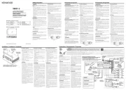
7 Speaker selection
• Using speakers with smaller input ratings than the
amplifier’s output power would result in smoke
generation or equipment failure.
• The impedance of the speakers that are going to
be connected should be 2 or greater (for stereo
connections, amplifier SUB), or 4 or greater (for bridged
connections). When more than one set of speakers are
going to be used, calculate the combined impedance of
the speakers and then connect suitable speakers to the
amplifier.
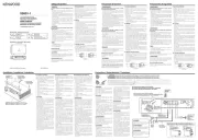
<Example>
Combined impedance
Installation / 安装 Connection / 连接
7
Installation procedure
Since there are large variety of settings and
connections possible according to applications,
read the instruction manual well to select the
proper setting and connection.
1. Remove the ignition key and disconnect the
negative · terminal of the battery to prevent
short circuits.
2. Set the unit according to the intended usage.
3. Remove the Dressing cover.
4. Connect the input and output wires of the
units.
5. Connect the speaker wires.
6. Connect the power wire, power control wire
and grounding wire following this order.
7. Install the installation fittings in the unit.
8. Attach the unit.
9. Attach the Dressing cover.
10. Connect the negative terminal of the ·
battery.
CAUTION
• Do not install in the below locations;
(Unstable location, In a location that interferes
with driving, In a location that gets wet, In a
dusty location, In a place that gets hot, In a place
that gets direct sunlight, In a location that gets
hit by hot air)
• Do not install the unit under the carpet.
Otherwise heat build-up occurs and the unit
may be damaged.
• Install this unit in a location which allows heat to
easily dissipate.
Once installed, do not place any object on top
of the unit.
• The surface temperature of the amplifier will
become hot during use. Install the amplifier in a
place where people, resins, and other substances
that are sensitive to heat will not come into
contact with it.
• This unit has cooling fan to decrease the internal
temperature. Do not mount the unit in a place
where the cooling fan and ducts of the unit are
blocked. Blocking these openings will inhibit the
cooling of the internal temperature and result in
malfunction.
• When making a hole under a seat, inside the
trunk, or somewhere else in the vehicle, check
that there is nothing hazardous on the opposite
side such as a gasoline tank, brake pipe, or wiring
harness, and be careful not to cause scratches or
other damage.
• Do not install near the dashboard, rear tray, or air
bag safety parts.
• The installation to the vehicle should securely
fasten the unit to a place in which it will not
obstruct driving. If the unit comes off due to a
shock and hits a person or safety part, it may
cause injury or an accident.
• After installing the unit, check to make sure that
electrical equipment such as the brake lamps,
turn signal lamps and windshield wipers operate
normally.
7 安装步骤
根据使用场合的不同,可能有多种不同的连接及设
定方式请务必仔细阅读使用说明书,选择适当的连
接和设定。
1. 拔取点火钥匙,拆掉蓄电池负极 端子,以防短·
路。
2. 根据使用目的,设置本机到妥当位置。
3. 去掉装饰板。
4. 连接本机的输入和输出缆线。
5. 连接扬声器缆线。
6. 连接电源线,电源控制缆线及地线,不可违反此
顺序。
7. 向本机安装装配部件。
8. 安装本机。
9. 装上装饰板。
10. 连接蓄电池的负极 。·
注意
・ 不得在下列位置安装;
(不稳定的位置,妨碍驾驶车辆的位置,潮湿的
位置,灰尘较多的位置,受热的位置,阳光直射
的位置,热气接触的位置)
・ 不可将本装置安装在绒毯底下, 否则,蓄热会导
致本装置损坏。
・ 将本装置安装在热量容易发散的地点。
一旦安装完毕,不可在其上放置其它物品。
・ 机器使用过程中,机体表面会发热升温。 所以其
安装地点应该是人体,树脂及其它热敏感物质不
易触及的地方。
・ 本装置设有冷却风扇用来降低内部温度。 请不要
安装在遮挡冷却风扇和风管的位置。 堵塞通风孔
的后果是内部温度升高,引起系统故障。
・ 在车座,行李箱底部或车子其它部位打孔时,应
确认其背面有没有会受到损坏的物件,诸如油
箱、刹车用配管或线路管套等,千万不可擦伤或
损坏这些物品。
・ 不可安装在驾驶室仪表板,尾部底板或保险气囊
等部件之上。
・ 将本机安装在车内时,应确保固定牢靠,且不会
对驾车造成妨碍。 如果因为冲击造成本机脱落且
撞及人体或保险部件,就会导致伤害或事故。
・ 在本装置安装之后,应该确认电气设备,比如刹
车灯、转向信号灯以及雨刷等操作正常。
WARNING Remove the ignition key and disconnect the negative · terminal of the
battery to prevent short circuits.
警告 拔取点火钥匙,拆掉蓄电池负极 端子,以防短路。·
WARNING
Particular attention must be given to making good
electrical contact at the amplifier-output and speaker
terminals.
Poor or loose connections can cause sparking or
burning at the terminals because of the very high
power that the amplifier can deliver.
CAUTION
• If sound is not output normally, immediately turn power
off and check connections.
• Be sure to turn the power off before changing the setting
of any switch.
• If the fuse blows, check wires for shorts, then replace the
fuse with one of the same rating.
• Check that no unconnected wires or connectors are
touching the car body. Do not remove caps from
unconnected wires or connectors to prevent short
circuits.
• Connect the speaker wires to appropriate speaker
connectors separately. Sharing the negative wire of the
speaker or grounding speaker wires to the metal body of
the car can cause this unit to fail.
• After installation, check that the brake lamps, turn signal
lamps and windshield wipers work properly.
警告
要特别注意放大器的输出口和扬声器端子处有良好的电气
接触。
因为放大器要发出非常高的功率,松弛或不良的连接可能
在端子处产生火花甚至燃烧。
注意
・ 如果声音输出不正常,应立即关断电源并检查连接是否正
确。
・ 在变更开关的设定时,必须首先切断电源。
・ 当保险丝熔断后,要检查缆线是否有短路,并更换上相同
规格的保险丝。
・ 检查是否有尚未连接的缆线或与车体相接触的端头。 未
连接缆线及其端部的保护帽不可拆掉,以防短路。
・ 扬声器的缆线要分别连接到各自的端子。 共用扬声器的
负极缆线或将扬声器端子接地到汽车的金属部分,都会导
致本机停止工作。
・ 安装之后,请检查汽车的刹车灯、方向指示灯、雨刷等是
否正常动作。
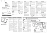
WARNING
To prevent fire caused by a short in the wiring,
connect a fusible link or breaker nearby the
battery’s positive terminal.
警告
为了防止短路所引起的火灾,在蓄电池的正极附近
连接保险丝或断电器。
7
Power wire and speaker wire connection
7
电源线和扬声器线的连接
Center unit (CD receiver, etc.)
中心装置(CD 接收机等)
B64-5065-00/00 ( WV)© 2012 JVCKENWOOD Corporation
XR900-5
CLASS D FIVE CHANNEL POWER AMPLIFIER
INSTRUCTION MANUAL
5声道D类功率放大器
使用说明书
安全注意事项
警告
为了防止受伤和火灾,请遵守下列注意事项。
• 安装本产品和连接导线需要一定的技能和经验。为了保证安
全,应请专业人员完成安装和连接导线作业。
• 当延长蓄电池导线和接地导线时,请使用车辆用导线
14mm2(AWG 6)~21mm2(AWG 4)之间的导线,以防止
导线劣化和被覆面的损伤。
• 为了防止短路等事故,请勿将金属物品(硬币,工具等)掉
落在装置中。
• 万一装置冒烟或有异味时,请立即关闭电源,并与建伍经销
商洽谈。
• 在使用中请尽量不要接触装置表面。因为装置在使用中表面
发热会烫伤人体。
注意
为了防止装置发生故障,请遵守下列注意事项,正确操作和
使用。
• 请以负接地线的12V直流电源向本装置供电。
• 请勿打开顶部和底部的盖子。
• 请勿将本装置安装在曝露于直射阳光,高温或高湿, 水可
能飞溅的或有灰尘的地方。
• 更换保险丝时,请更换规定容量相同的保险丝, 如使用不
同容量的保险丝,可能会造成装置的故障。
• 更换保险丝时,为了防止短路事故,请先拔下电源线束再进
行更换。
注
• 安装有困难时,请与建伍经销商洽谈。
• 如果仍不能恢复正常时,请与建伍经销商洽谈。
装置的保养
如果外表污脏时,请关闭电源,使用干燥的硅布或柔软的布
匹擦拭。
注意
请勿使用硬布或涂料稀释剂,酒精等挥发性溶剂, 以免损坏
外表面或将所附指示字符擦掉。
防止蓄电池全部放电
当本机在ACC ON位置使用而不开动发动机时,将消耗蓄电池
的电量。 请在开动了发动机之后使用。
保护功能
在以下场合中保护功能被激活
本机装有保护功能,可以保护本机以及扬声器不会受到可能
发生的各种意外事故的损害。
当保护功能被触发时,电源指示灯将熄灭,放大器也停止工
作。
• 当扬声器缆线短路时。
• 当扬声器的输出接地时。
• 当本机出现误动作,有 DC(直流) 信号传送到扬声器输出
端时。
• 内部高温不能动作时。
7 接线
• 请将本机的蓄电池连接线直接与蓄电池连接。 如果与汽车
的配线束连接,将产生烧毁保险丝等故障。
• 如果发动机运转时从扬声器中发出噪音,可以在蓄电池的每
根连线上加一个线路噪音滤波器(选购件)。
• 使用保护套,以防缆线直接接触铁板的边缘。
• 将接地线连接到车架的金属部位,车架起到车辆电气接地的
作用,将电流传递到蓄电池的负极 。 如果接地线没有连·
接就不要打开电源开关。
• 应务必在蓄电池附近的电源连接线上设置保险丝。 保险丝
的规格应该与本机的保险丝容量相同或者略大。
• 对于电源连接线和接地线,请使用电流容量大于本机保险
丝容量的汽车用(防火)电源连接线。 (请使用截面积
为14mm2(AWG 6)~21mm2(AWG 4)之间的电源连接
线。)
• 当使用多个功率放大器时,电源导线的电流容量及保险丝的
容量要大于各个放大器的使用电流之和的最大值。
7 扬声器选择
• 使用输入额定值比放大器输出功率小的扬声器将会导致冒烟
或设备故障。
• 所连接的扬声器的阻抗必须为 2 欧姆或更高(立体声连接
时、SUB放大器);或者 4 欧姆或更高(桥接连接)。 当
使用一组扬声器时,必须在计算扬声器的 总阻抗之后,再
连接合适的扬声器。
<例>