56417
Rechargeable Dual-Beam Area Light -
Instructions
Luz de área recargable con doble haz de luz -
Instrucciones
Lampe rechargeable à éclairage général et à deux
faisceaux–
Instructions
ESPAÑOL FRANÇAISENGLISH
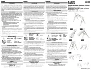
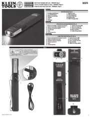
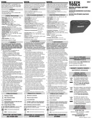
The 56417 Dual-Beam Area Light is a rechargeable spot light/flood light
duo with a flat base and multiple mounting options, including strong
magnets, 360˚ rotating hanging hook, and MODbox-compatible mounts.
The lights rotate 360˚ for unique lighting angles and allows for the spot and
flood light to be adjusted individually where each is needed. This compact,
rugged, drop-rated area light is designed for active daily professional use.
CONTENTS
• 56417 Rechargeable Dual-Beam Work Light
• 6' (1.83 m) USB-C cable
• This instruction sheet
GENERAL SPECIFICATIONS
• Operating/Storage Altitude: 6562 ft. (2000 m)
• Operating Temperature: 5°F to 104°F (-15°C to 40°C)
• Charging Temperature: 41°F to 95°F (5°C to 35°C)
• Storage Temperature: -4°F to 140°F (-20°C to 60°C)
• Relative Humidity: <85% non-condensing
• Lighting Mode Specications:
All-On: 3000 Lumens, 3 hrs.
Spot Light: HIGH: 1400 Lumens, 5 hrs. LOW: 475 Lumens, 9.5 hrs.
Flood Light: HIGH: 1400 Lumens, 8 hrs. MEDIUM: 700 Lumens, 10 hrs.
LOW: 250 Lumens, 12 hrs.
• Battery Cell Type: 18650, Lithium-Ion (×2)
• Battery Capacity: 6700mAh (24Wh)
• Charging Time: Full charge in approx. 3 to 6 hours
• Shelf Life: Up to 2 years if fully charged. Charge as needed, at least
once per year recommended.
• Charging Requirements: (USB-C): DC 5V, Max. 2A
• Output: (USB-A): DC 5V, Max. 2.4A
• Dimensions: 5.2" × 7.6" × 3.5" (132 × 193 × 89 mm)
• Weight: 2.2 lb. (998 g)
• Drop Protection: 9.8 ft. (3 m)
• Ingress Protection Rating: IP65
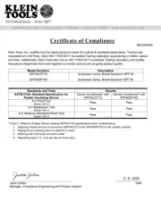
• Standards / Certications:
CE, UKCA, REACH, RoHS, DOE/CEC, NRCAN
Certified to UL 1576, CSA C22.2 No. 250.5
Specifications subject to change.
WARNINGS
Read, understand, and follow these instructions to ensure safe
operation. Failure to observe these warnings can result in risk of fire,
electric shock, serious injury and/or property damage.
• The lens gets very hot during use. To reduce the risk of burns, DO
NOT touch hot lens.
• To reduce the risk of fire, keep away from combustible materials while
in operation. DO NOT cover lens. Ensure that proximity sensor is
clear of any debris before use.
• DO NOT use the product if it is damaged or modified. Damaged or
modified batteries may exhibit unpredictable behavior resulting in fire,
explosion, or injury.
• Risk of fire and burns. DO NOT open, crush, heat above specified
maximum temperature or incinerate. Prolonged exposure to direct
sunlight can result in elevated temperatures
• DO NOT immerse in water or other liquids
• Properly seal the charging port cover to achieve specified water &
foreign object ingress protection. Keep seal free of dirt, oil, sand, or
other material that interferes with proper sealing. Failure to do so can
result in risk of fire or electric shock.
• DO NOT open the charging port cover if wet or in a wet environment.
Thoroughly dry the unit and the seal around water-resistant cover
completely before opening water resistant cover
• DO NOT subject to impacts or drops greater than 9.8 ft. (3 m)
(Product Drop Rating). Drops larger than this may not show signs of
damage, but internal components may have been compromised. It is
advisable to replace the unit if any such severe events occur
• Use safety-rated power supply or wall adapter. Never use power
supply or wall adapter that exceeds the specified charging voltage
and current.
• DO NOT stare at Operating Lamp.
• Strong Magnetic Field.
• Not a tether point: Not for dropped object prevention
• DO NOT attempt to repair the product, battery, or charging cable
except as indicated in the MAINTENANCE section.
FCC AND IC COMPLIANCE:
See this product’s page at www.kleintools.com for FCC compliance
information.
Canada ICES-003 (B) / NMB-003 (B)
MAINTENANCE
CLEANING: Be sure device is disconnected from all power sources
and devices. Use clean, dry, soft, lint-free cloth to wipe down the
entire unit.
DO NOT use abrasive cleaners or solvents.
STORAGE:
• If storing for more than one month, charge completely before
storage, and recharge approximately every three months to avoid full
discharge. Store in cool temperatures, mild humidity, and away from
direct sunlight (See GENERAL SPECIFICATIONS).
• Leaving in a vehicle or other confined spaces in extreme hot
temperatures can lead to decrease in service life, overheating, or fire.
Extreme cold temperatures below the specified storage range can
also harm performance and service life. Keep away from corrosive
chemicals and gases.
• After taking out of storage, inspect visually to make sure device and
all accessories look satisfactory. Allow unit to return to ambient
conditions before recharging or charging other devices.
RECHARGING:
• Recharge as needed. There are no pre-designated intervals at which
to recharge as long as you are using regularly. Avoid discharging
completely on a regular basis, as this can impact overall life.
Regularly inspect ports and charging cable for any debris, dirt,
damage, and corrosion. attempt to fix. Replace device and/DO NOT
or cable as needed.
TROUBLESHOOTING
56417 will NOT charge IF:
• The cable is not properly connected to charger output or battery
input.
Check connection
.
• The charging cable is damaged.
Replace with equivalent cable
.
• The charging port or device is not able to supply the minimum voltage
and current for charging.
Connect to appropriate charging source
.
• The charger is damaged.
Replace charger.
WARRANTY
www.kleintools.com/warranty
DISPOSAL / RECYCLE
Do not place equipment and its accessories in the trash.
Items must be properly disposed of in accordance with local
regulations. Please see www.epa.gov recycle/ for additional
information.
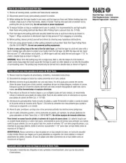
OPERATING INSTRUCTIONS
SEE OTHER SIDE.
1390652 Rev 08/24 A
CUSTOMER SERVICE
SERVICIO AL CLIENTE
SERVICE À LA CLIENTÈLE
KLEIN TOOLS, INC.
450 Bond Street Lincolnshire, IL 60069
1-800-553-4676
customerservice@kleintools.com
www.kleintools.com
EN ERG Y VE RI FI ED
B0102
La luz de área con doble haz de luz 56417 es una combinación de luz enfocada
y luz de proyección recargable con una base plana y múltiples opciones de
montaje que incluyen imanes potentes, gancho de colgar con giro de 360º y
montajes compatibles con MODbox™. Las luces rotan 360º para conseguir
ángulos de iluminación únicos y permiten ajustar la luz enfocada y la luz de
proyección individualmente donde cada una sea más necesaria. Esta luz de
área compacta, resistente, y a prueba de caídas está diseñada para un uso
profesional, activo y diario.
CONTENIDO
• Luz de trabajo recargable con doble haz de luz 56417
• Cable USB-C de 6' (1,83m)
• Esta hoja de instrucciones
ESPECIFICACIONES GENERALES
• Altitud de funcionamiento y almacenamiento: 6562' (2000m)
• Temperatura de funcionamiento: 5°F a 104°F (-15°C a 40°C)
• Temperatura de carga: 41°F a 95°F (5°C a 35°C)
• Temperatura de almacenamiento: -4°F a 140°F (-20°C a 60°C)
• Humedad relativa: <85%, sin condensación
• Especicaciones del modo de iluminación:
Todas las luces encendidas: 3000lúmenes, 3h
Luz enfocada: ALTO: 1400lúmenes, 5h BAJO: 475lúmenes, 9,5h
Luz de proyección: ALTO: 1400lúmenes, 8h MEDIO: 700lúmenes, 10h
BAJO: 250lúmenes, 12h
• Tipo de celda de la batería: 18650, iones de litio (×2)
• Capacidad de la batería: 6700mAh (24Wh)
• Tiempo de carga: carga completa en aprox. 3 a 6horas
• Vida útil de almacenamiento: hasta 2años si está completamente
cargada. Cárguela según sea necesario, se recomienda hacerlo al menos
una vez al año.
• Requisitos de carga: (USB-C): 5VCD, máx. 2A
• Salida: (USB-A): 5VCD, máx. 2,4A
• Dimensiones: 5,2"×7,6"×3,5"(132×193×89mm)
• Peso: 2,2lb (998g)
• Protección ante caídas: 9,8' (3m)
• Grado de protección de ingreso: IP65
• Normas/certicaciones: CE, UKCA, REACH, RoHS, DOE/CEC, NRCAN
Certificado según UL 1576, CSA C22.2 n.º 250.5
Especificaciones sujetas a cambios.
ADVERTENCIAS
Lea, comprenda y siga estas instrucciones para garantizar un funcionamiento
seguro. El incumplimiento de estas advertencias puede provocar riesgo de
incendio, choque eléctrico, lesiones personales y/o daños materiales graves.
• La lente se calienta demasiado durante el uso. Para reducir el riesgo
dequemaduras, NO toque la lente caliente.
•Para reducir el riesgo de incendio, manténgala lejos de materiales inflamables
mientras está en funcionamiento. NO cubra la lente. Asegúrese de que el
sensor de proximidad esté libre de residuos antesdel uso.
• NO use el producto si está dañado o p1-ha sido modificado. Las baterías dañadas
o modificadas pueden presentar comportamientos impredecibles que pueden
provocar incendios, explosiones o lesiones.
• Riesgo de incendio y quemaduras. NO lo abra, aplaste, caliente a más de la
temperatura máxima especificada, ni lo incinere. La exposición prolongada a la
luz solar directa puede provocar temperaturas elevadas
• NO lo sumerja en agua u otros líquidos
•Selle correctamente la cubierta del puerto de carga para lograr la protección
especificada contra el ingreso de agua y objetos extraños. Procure que el
sello no contenga suciedad, aceite, arena u otros materiales que afecten
un sellado adecuado. De lo contrario, puede provocar riesgo de incendio
ochoque eléctrico.
• NO abra la cubierta del puerto de carga si está húmeda o si está en un ambiente
húmedo. Seque cuidadosamente la unidad y el sello alrededor dela cubierta
resistente al agua antes de abrir la cubierta resistente alagua.
• NO lo someta a impactos o caídas mayores que 9,8' (3m) (producto con
resistencia a las caídas). Es posible que caídas mayores a esta altura no
muestren señales de daño, pero los componentes internos podrían estar
comprometidos. Se recomienda reemplazar la unidad si sufre alguno de estos
eventos de gravedad.
• Use una fuente de alimentación o adaptador de pared con clasificación de
seguridad. Nunca use una fuente de alimentación o adaptador de pared que
supere el voltaje y la corriente de carga especificados.
• NO mire fijamente la luz frontal cuando esté en funcionamiento.
• Fuerte campo magnético.
• No es un punto de sujeción: no evita caídas de objetos.
• NO intente reparar el producto, la batería ni el cable de carga, excepto como se
indica en la sección MANTENIMIENTO.
CONFORMIDAD CON LA NORMATIVA FCC/IC:
Puede leer la información sobre la normativa FCC para este producto en
www.kleintools.com.
ICES-003 (B)/NMB-003 (B) de Canadá
MANTENIMIENTO
LIMPIEZA: asegúrese de que el dispositivo esté desconectado decualquier fuente
de energía o dispositivo. Utilice un paño limpio, seco y suave que no deje pelusas
para limpiar toda la unidad.
NO utilice solventes nilimpiadores abrasivos.
ALMACENAMIENTO:
•Si lo almacena por más de un mes, cárguelo completamente antes
de almacenarlo, y recárguelo aproximadamente cada tres meses
para evitar que se descargue completamente. Almacénelo en un
ambiente fresco, con humedad leve y lejos de la luz solar directa
(verESPECIFICACIONESGENERALES).
•Si lo deja en un vehículo o en otros espacios reducidos bajo temperaturas
extremadamente altas, se puede reducir su vida útil, provocar
sobrecalentamiento o un incendio. Las temperaturas extremadamente frías,
por debajo del rango de almacenamiento especificado, también pueden
afectar el rendimiento y la vida útil. Manténgalo alejado de gasesy sustancias
químicas corrosivas.
• Después de retirarlo del almacenamiento, inspeccione visualmente el dispositivo
para asegurarse de que su apariencia y la de todos sus accesorios es correcta.
Permita que la unidad regrese a condiciones deambiente antes de recargarla
ocargar otros dispositivos.
RECARGA:
• Recárguela según sea necesario. No hay intervalos predefinidos según los
cuales se deba recargar, siempre y cuando use la batería regularmente. Evite
descargarla completamente de manera regular, yaque esto puede afectar su
vida útil general. Inspeccione regularmente los puertos y el cable de carga,
verificando que no tenganresiduos, suciedad, daños y corrosión. intenteNO
repararla. Reemplace el dispositivo y/o cable, segúnsea necesario.
SOLUCIÓN DE PROBLEMAS
La 56417 NO cargará SÍ:
• El cable no está conectado adecuadamente a la salida del cargador
oala entrada de la batería.
Revise la conexión
.
• El cable de carga está dañado.
Reemplácelo con un cable similar
.
• El dispositivo o puerto de carga no puede proporcionar la corriente y el
voltaje mínimos para cargar.
Conecte a una fuente de carga adecuada
.
• El cargador está dañado.
Reemplace el cargador.
GARANTÍA
www.kleintools.com/warranty
ELIMINACIÓN/RECICLAJE
No arroje el equipo ni sus accesorios a la basura. Los elementos se
deben desechar correctamente de acuerdo con las regulaciones locales.
Para obtener más información, consultewww.epa.gov recycle/ .
INSTRUCCIONES DE FUNCIONAMIENTO
VEA EL REVERSO.
La lampe à éclairage général et à deux faisceaux56417 est une lampe
rechargeable à deux modes d’éclairage avec une base plate et de nombreuses
options de montage, y compris des aimants puissants, un crochet rotatif à
360degrés et des fixations compatibles avec MODbox. La lampe éclaire sur
360degrés, ce qui offre des angles d’éclairage uniques. Les faisceaux concentrés
et à éclairage général peuvent être réglés individuellement quand c’est nécessaire.
Cette lampe à éclairage général compacte, robuste et résistante aux chutes est
conçue pour une utilisation professionnelle au quotidien.
CONTENU
• Lampe de travail rechargeable à deux faisceaux56417
• Câble USB-C de 1,83m (6pi)
• Feuillet d’instructions
CARACTÉRISTIQUES GÉNÉRALES
• Altitude de fonctionnement ou d’entreposage: 2000m (6562pi)
• Température de fonctionnement: -15 à 40°C (5 à 104°F)
• Température de recharge: 5 à 35°C (41 à 95°F)
• Température d’entreposage: -20 à 60°C (-4 à 140°F)
• Humidité relative: <85% sans condensation
• Caractéristiques du mode d’éclairage
Éclairage amplié: 3000lumens, 3heures
Faisceau concentré: NIVEAU ÉLEVÉ: 1400lumens, 5heures
NIVEAUFAIBLE: 475lumens, 9,5heures
Faisceau à éclairage général: NIVEAU ÉLEVÉ: 1400lumens, 8heures
NIVEAU MOYEN: 700lumens, 10heures
NIVEAU FAIBLE: 250lumens, 12heures
• Type de batterie: batterie18650 au lithium-ion (×2)
• Capacité de la batterie: 24Wh (6700mAh)
• Temps de recharge: recharge complète en environ 3 à 6heures
• Durée d’entreposage: jusqu’à 2ans lorsque la lampe est entièrement
rechargée. Rechargez au besoin, au moins une fois par année.
• Exigences de recharge: USB-C: 5V c.c, max. 2A
• Sortie: USB-A: 5V c.c, max. 2,4A
• Dimensions: 132×193×89mm (5,2×7,6×3,5po)
• Poids: 998g (2,2lb)
• Protection contre les chutes: 3m (9,8pi)
• Cote de protection contre les inltrations: IP65
• Normes/certications: CE, UKCA, REACH, ROHS, DOE/CEC et RNCan
Certifié conforme aux normesUL 1576 et
CSAC22.2 nº 250.5
Les caractéristiques techniques peuvent faire l’objet de modifications.
AVERTISSEMENTS
Veuillez lire, comprendre et suivre ces instructions afin de garantir une utilisation
sécuritaire. Le non-respect de ces avertissements peut entraîner un risque
d’incendie, de choc électrique, de blessures graves ou de dommages matériels.
•
Le verre devient très chaud pendant l’utilisation. Pour réduire le risque de brûlures,
NE TOUCHEZ PAS le verre chaud.
•Pour réduire le risque d’incendie, tenez la lampe à l’écart de tout matériau
combustible lorsqu’elle est allumée. NE COUVREZ PAS le verre. Assurez-vous
quele capteur de proximité est exempt de tout débris avant l’utilisation.
•N’UTILISEZ PAS le produit s’il est endommagé ou modifié. Des batteries
endommagées ou modifiées risquent de produire des effets imprévisibles
etdecauser des incendies, des explosions ou des blessures.
• Risque d’incendie et de brûlures. N’OUVREZ PAS ce produit, ne l’écrasez pas,
ne le chauffez pas à plus de la température maximale indiquée et ne le brûlez
pas. Une exposition prolongée à la lumière directe du soleil peut entraîner des
températures élevées.
• N’IMMERGEZ PAS ce produit dans l’eau ni dans tout autre liquide.
•
Scellez adéquatement le couvercle du port de recharge pour garantir la protection
prévue contre les infiltrations d’eau et de corps étrangers. Retirez du joint les saletés,
l’huile, le sable ou tout autre matériau qui pourrait nuire à l’étanchéité du capuchon.
Autrement, il pourrait y avoir un risque d’incendie ou de choc électrique.
•
N’OUVREZ PAS le couvercle du port de recharge s’il est mouillé ou si vous vous
trouvez dans un environnement humide. Laissez sécher complètement l’appareil
ainsi que le joint entourant le capuchon étanche avant d’ouvrir ce dernier.
•
N’EXPOSEZ PAS l’appareil à des chocs ni à des chutes de plus de 3m (9,8pi), soit
le coefficient de chute du produit. Après une telle chute, le boîtier pourrait sembler
intact même si les composants internes sont endommagés. Il est recommandé de
remplacer l’appareil s’il est soumis à de telles conditions
• Utilisez un bloc d’alimentation ou un adaptateur mural avec une cote de
sécurité. N’utilisez jamais un bloc d’alimentation ou un adaptateur mural qui
excède la tension de recharge et l’intensité de courant électrique indiquées.
• NE REGARDEZ PAS directement la lampe lorsqu’elle est allumée.
• Le produit émet un puissant champ magnétique.
• Le produit ne comporte aucun point d’attache: produit non conçu pour prévenir
les chutes d’objets.
• N’ESSAYEZ PAS de réparer le produit, la batterie ou le câble de
recharge, sauf selon les indications de la section ENTRETIEN.
CONFORMITÉ FCC ET IC
Consultez la page de ce produit à l’adresse www.kleintools.com pour obtenir des
renseignements sur la conformité à la Federal Communications Commission (FCC).
CanadaICES-003(B)/ NMB-003(B)
ENTRETIEN
NETTOYAGE : Assurez-vous de débrancher l’appareil de toute source
d’alimentation et de tout autre appareil. Utilisez un linge propre, sec et non
pelucheux pour essuyer tout l’appareil.
N’utilisez PAS de nettoyant abrasif
nide solvant.
ENTREPOSAGE:
•Si l’appareil doit être entreposé pour plus d’un mois, rechargez-le
complètement avant de le ranger et refaites-le environ aux trois mois pour
éviter une décharge complète. Rangez l’appareil au frais et au sec, loin
de la lumière directe du soleil (consultez la section CARACTÉRISTIQUES
GÉNÉRALES).
•Laisser l’appareil dans un véhicule ou un autre espace clos soumis à des
chaleurs extrêmes risque d’écourter sa durée de vie, de le faire surchauffer
ou de causer un incendie. Les températures froides inférieures à la plage
recommandée pour l’entreposage peuvent également écourter la durée
deviede l’appareil et nuire à son rendement. Gardez l’appareil éloigné
desproduits chimiques et des gaz corrosifs.
• Après les avoir entreposés, inspectez visuellement l’appareil et ses accessoires
pour vous assurer qu’ils sont dans un état acceptable. Laissez l’appareil
reprendre la température ambiante avant de le recharger ou de l’utiliser
pourrecharger d’autres appareils.
RECHARGE:
•Rechargez au besoin. Il n’y a aucun intervalle idéal établi pour recharger
l’appareil, pourvu qu’il soit utilisé fréquemment. Évitez de trop souvent
décharger complètement l’appareil: vous risqueriez d’écourter sa durée de
vie. Inspectez régulièrement les ports et le câble de recharge pour déceler la
présence de débris, de saleté, de dommages et de corrosion. N’ESSAYEZ PAS
de réparer cet appareil. Remplacez le câble ou l’appareil lorsque nécessaire.
DÉPANNAGE :
La lampe56417 ne peut PAS se recharger dans les cas suivants:
• Le câble n’est pas correctement branché au port de sortie du chargeur ou au
port d’entrée de la batterie.
Vériez le branchement.
• Le câble de chargement est endommagé.
Remplacez-le par un câble équivalent.
• Le port ou l’appareil de chargement n’est pas en mesure de fournir la tension et le
courant minimaux nécessaires pour le chargement.
Branchez le chargeur à une
source de chargement appropriée.
• Le chargeur est endommagé.
Remplacez le chargeur.
GARANTIE
www.kleintools.com/warranty
MISE AU REBUT/RECYCLAGE
Ne mettez pas l’appareil et ses accessoires au rebut. Ces articles doivent
être éliminés conformément aux règlements locaux. Pour de plus amples
renseignements, consultez le site www.epa.gov recycle/ .
INSTRUCTIONS D’UTILISATION
CONSULTEZ LE VERSO.