Kramer 676T Manual


Læs gratis den danske manual til Kramer 676T (4 sider) i kategorien AV forlænger. Denne vejledning er vurderet som hjælpsom af 11 personer og har en gennemsnitlig bedømmelse på 5.0 stjerner ud af 6 anmeldelser. Har du et spørgsmål om Kramer 676T, eller vil du spørge andre brugere om produktet?

Side 1/4
676T, 676R Quick Start
P/N:
2900- 301397QS
Rev:
4
Scan for full manual
Step 1: Check whats in the b ox
676T HDMI Optical Transmitter or
676R HDMI Optical Receiver
1 Bracket set
4 Rubber feet
1 Power cord and adapter
1 Quick start guide
1 OSP-MM1 Fiber Optic SFP+ Transceiver
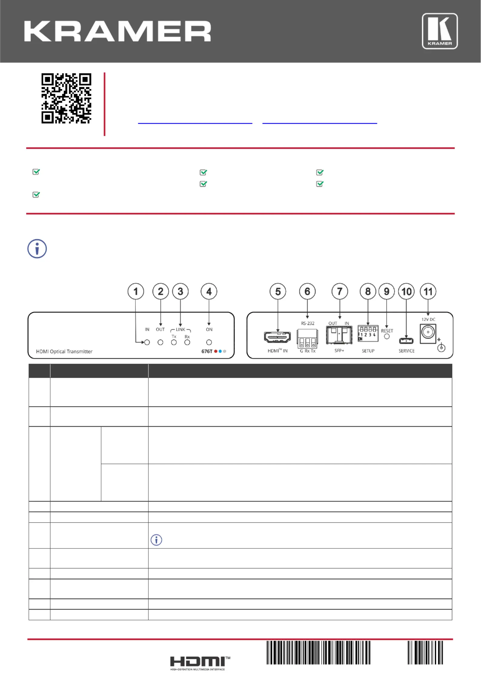
Step 2: Get to know your 676T and 676R
676T can be connected to a single 676R device or to multiple devices via optical splitters. When multiple devices are connected, a
receiver device is dened as primary when its Tx (SFP+ OUT) optical ber is connected directly to the 676T Rx optical fiber (SFP+ IN).
676T
#
Feature
Function
1
IN LED
Lights green when a connected source device (with an active HDMI signal) is detected.
Flashes 4 times green when resetting the device.
O when active signal is detected on the connected HDMI source device. no
2
OUT LED
Lights green when an HDMI acceptor device (with an active HDMI signal) detected. is
O when no active signal is detected on the connected acceptor.
3
LINK LEDs
Tx
Lights green when OUT IN SFP+ is connected, and an active Tx optical link is detected.
Lights red when OUT IN SFP+ is connected, and a fault is detected on the single/primary
676R receiving optical link.
O when the OUT IN SFP+ is disconnected.
Rx
Lights green when OUT IN SFP+ is connected, and an active optical link is detected. Rx
Lights red when OUT IN SFP+ is connected, and a fault is detected on the incoming optical
link.
O when OUT IN SFP+ is disconnected.
4
ON LED
Lights green when the device receives power.
5
HDMI™ IN Connector
Connect to an HDMI source.
6
RS- (Tx, Tr, G) 3-pin 232
Terminal Block Connector
Connect to a serial controller to communicate serial with all the connected receivers. ly
Receives -232 communication only from a single/primary receiver. RS
7
OUT IN SFP+ Connector
Connect the ber optic cable to the plugged- SFP+ optical module connectors. in
(OSP-MM1, included).
8
SETUP 4-way DIP-switch
Sets the device behavior.
9
RESET Recessed Button
Press and hold for 5 seconds or less to reset the device.
Press and hold for over 5 seconds to reset the device to factory default values.
10
SERVICE Micro USB Port
Connect to a PC to perform rmware upgrade (via K-Upload).
11
12V DC Power Connector
12V DC connector for powering the unit.
676R
#
Feature
Function
12
IN LED
Lights green when a connected HDMI source device (with an active HDMI signal) is
detected.
Flashes 4 times green when resetting the device.
O when no active signal is detected on the connected source device.
IN LED is always ofor receivers other than the single/primary device.
676R
13
OUT LED
Lights green when an HDMI acceptor device (with an active HDMI signal) is
detected on the single/primary 676R device.
O when no active signal is detected on the connected acceptor.
14
LINK LEDs
Tx
Lights green when OUT IN SFP+ is connected, and an active Tx optical link is
detected.
Lights red when OUT IN SFP+ is connected, and a fault is detected on the 676T
receiving optical link.
LED on devices other than the single/primary Tx 676R device always light red.
O when OUT IN SFP+ is disconnected.
Rx
Lights green when OUT IN SFP+ is connected, and an active optical link is Rx
detected.
Lights red when OUT IN SFP+ is connected, and a fault is detected on the incoming
active optical link.
O when OUT IN SFP+ is disconnected.
15
ON LED
Lights green when the device receives power.
16
HDMIOUT Connector
Connect to an HDMI acceptor.
17
RS-232 (Tx, Tr, G) 3-pin Terminal
Block Connector
Connect to the serial control port of a controlled device located next to the 676R.
Only the controlled device connected to the single/primary receiver returns
serial data to the transmitter.
18
OUT IN SFP+ Connector
Connect the ber optic cable to the plugged-in SFP+ optical module connectors
(OSP-MM1, Included ).
19
SERVICE Micro USB Port
Connect to a PC to perform rmware upgrade via K-Upload.
20
12V DC Power Connector
12V DC connector for powering the unit.
Step 3: Mount /676R 676T
Install 676T/676R using one of the following methods:
Attach the rubber feet and place the unit on a at surface.
Fasten a bracket (included) on each side of the unit and attach it to a at surface
(see www.kramerav.com/downloads/676T).
Mount the unit in a rack using the recommended rack adapter
(see www.kramerav.com/product/676T).
Ensure that the environment (e.g., maximum ambient temperature &
air ow) is compatible for the device.
Avoid uneven mechanical loading.
Appropriate consideration of equipment nameplate ratings should be
used for avoiding overloading of the circuits.
Reliable earthing of rack-mounted equipment should be maintained.
Maximum mounting height for the device is 2 meters.


Produkt Specifikationer

Mærke: Kramer
Kategori: AV forlænger
Model: 676T

Har du brug for hjælp?

Hvis du har brug for hjælp til Kramer 676T stil et spørgsmål nedenfor, og andre brugere vil svare dig


AV forlænger Kramer Manualer

Kramer

Kramer EXT3-U3-T Manual

20 Januar 2025
Kramer

Kramer VP-427X2 Manual

19 December 2024
Kramer

Kramer TP-594Rxr Manual

19 December 2024
Kramer

Kramer TP-752R Manual

19 December 2024
Kramer

Kramer TP-780T Manual

19 December 2024
Kramer

Kramer TP-594Txr Manual

19 December 2024
Kramer

Kramer TP-752T Manual

19 December 2024
Kramer

Kramer TP-583Txr Manual

19 December 2024
Kramer

Kramer W-3H2 Manual

19 December 2024
Kramer

Kramer WP-872xr Manual

19 December 2024

AV forlænger Manualer

Nyeste AV forlænger Manualer