The Kramer SID- DisplayPort Step-In Commander DP
Congratulations on purchasing your Kramer DigiTOOLS
® SID-DP DisplayPort Step-In
Commander which is ideal for boardrooms and presentation rooms.
The Kramer is an HDCP compliant DisplayPort and unbalanced stereo audio SID-DP
remote device that used to remotely take control of a compatible switcher, for is
example, the Kramer . The commander does not need a power adapter if VP-81SID
located within 50m ( ft) of the switcher. 164
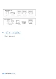
Figure 1 Table 1 and define the . SID- DP DisplayPort Step-In Commander
Figure 1 SID- DisplayPort Step-In Commander Front and Rear Panel : DP
Table 1 SID- DisplayPort Step-In Commander Front and Rear Panel Features : DP
AUDIO INPUT 3.5mm Mini Jack
Connect to the unbalanced stereo audio source
DP INPUT DisplayPort Connector
Connect to the video source DP
Press to switch the input to this remote control commander The .
button lights when active
Lights green when the unit receives power
LINE OUT Twisted Pair RJ-45
Connector
Connect to the TP input of compatible switcher (for example, the a
VP-81SID) using CAT 6 or higher specification cable
Remote Switch Terminal Block
Connections (pins 2 and 3)
Connect to the remote step-in switch
Connect to the power adapter
Remote LED Terminal Block
Connections (pins 1 and 2)
Connect to the remote LED (observe correct polarity, pin 1 to the
LED anode and pin 3 to the cathode)
Figure 2 illustrates how to connect the to a source switcher, and remote switch SID-DP ,
and LED.
Figure 2 SID- Wiring Connections : DP
To connect the SID- as illustrated in : DP Figure 2
1. Connect the DP video source (for example, a laptop graphics source to the )
DisplayPort connector on the front panel of the . SID-DP
2. Connect the unbalanced stereo audio source (for example, a laptop graphics source)
to the 3.5mm mini jack AUDIO INPUT connector on the front of the SID-DP.
3. Using STP cable, connect the LINE OUT RJ- TP connector on the rear panel of 45
the to the required input on the rear panel of the (up to 50m SID-DP VP-81SID
away).
4. Optional Connect the terminal block on the rear of the to the remote —S -ID DP
switch and LED.
Note: The LED supply includes a current limiting resistor and is designed to work
with any standard LED.
5. Connect the power adapter to the 12V DC connector on the rear of the and SID-DP
to the mains electricity (if the distance exceeds 50m ( ft) from the switcher). 164