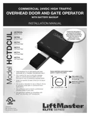
1
NOTE: The following images are for reference only. Your unit and shaft collar may
look different.
You may need:
• 3/8" (10 mm) Open End Wrench
• 3/16" (5 mm) Hex Key Wrench
Shaft Collar
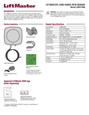
Model 041D8615
Included Items
Shaft Collar . . . . . . . . . . . . . . . . . . . . . . . . . . . . . . . . . . . . . . . . . . . . . . . . . . . . . (1)
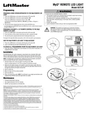
WARNING: This product can expose you to chemicals including
lead, which are known to the State of California to cause cancer or
birth defects or other reproductive harm. For more information go to
www.P65Warnings.ca.gov
To prevent possible SERIOUS INJURY or DEATH:
• Disconnect ALL electric and battery power BEFORE performing ANY service or
maintenance.
To prevent damage to the receiver logic board, DO NOT touch printed circuit
board of replacement receiver logic board during installation.
ALWAYS wear protective gloves and eye protection when changing the battery or
working around the battery compartment.
1. Close the
garage door.
2. Disconnect
power from
the outlet and
remove the battery
if applicable.
3. To remove the battery,
press the clip to remove
the connector from the
unit (A).
4. Remove wires from the
unit and label them for
reinstallation. Disconnect
wires from the quick
connect terminals (B).
5. Loosen the shaft collar.
Use a 3/16" (5mm) hex
key wrench to loosen the
shaft collar (C).
7. Using a 3/8" (10 mm) open
end wrench, remove the two
14-10 x 2" screws holding
the mounting bracket to the
wall .(E)
8. Remove the motor unit
from wall.
9. Discard the old shaft collar.
Battery
Backup Cord
475LM
Battery Backup
Connector
WHT/
BLK
WHT
A
B
Collar Screws
Shaft Collar
3/16" (5 mm)
Hex Key Wrench
Collar Screws Set Screws
C
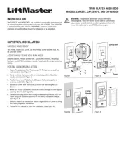
1. Close the garage door.
2. Disconnect power from
the outlet and remove the
battery if applicable.
3. Open the front panel (A).
4. Remove the battery cover.
Disconnect the battery (if
applicable). Remove the
battery and set aside (B).
5. Remove wires from the
unit and label them for
reinstallation.
Disconnect wires
from the quick
connect terminals (C).
6. Loosen the shaft collar.
Use a 3/8" (10 mm) open
end wrench to loosen the
shaft collar (D).
7. Using a 3/8" (10 mm) open end wrench,
remove the two 14-10 x 2" screws holding
the mounting bracket to the wall (E).
8. Remove the motor unit from wall.
9. Discard the old shaft collar.
Set Screws
Motor Shaft
Shaft Collar
Mounting Bracket
Screws
14-10 x 2"
E
A
B
C
D
Follow these steps for shaft collars
that install with a hex key wrench
Follow these steps for shaft collars
that install with an open end wrench