LiftMaster 050ACTBLKMC Manual
LiftMaster
Ikke kategoriseret
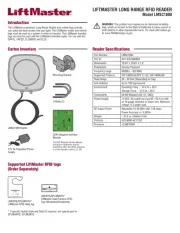
050ACTBLKMC

| Mærke: | LiftMaster |
| Kategori: | Ikke kategoriseret |
| Model: | 050ACTBLKMC |
Har du brug for hjælp?
Hvis du har brug for hjælp til LiftMaster 050ACTBLKMC stil et spørgsmål nedenfor, og andre brugere vil svare dig
Ikke kategoriseret LiftMaster Manualer

8 August 2025
7 August 2025
7 August 2025

7 August 2025
7 August 2025
7 August 2025

15 Juni 2025
4 September 2024

3 September 2024
3 September 2024
Ikke kategoriseret Manualer
- Waterco
- Xunzel
- Dobot
- Harman Kardon
- Zeapon
- Elvid
- Lupine
- DPW Design
- Wireless Solution
- Crathco
- Dynacord
- Aligator
- Randell
- Proficook
- P3 International
Nyeste Ikke kategoriseret Manualer

11 December 2025

11 December 2025

11 December 2025

11 December 2025

11 December 2025

11 December 2025

11 December 2025

11 December 2025

11 December 2025

11 December 2025