Swing Gate Operator Long Arm Kit
Model HDLGARM
To reduce the risk of SEVERE INJURY or DEATH:
• Disconnect power (AC solar and battery) before servicing or
installing operator.
• Turn both the AC and battery switches to off position.
• Set the reset switch to the disconnect position.
WARNING: This product can expose you to chemicals including
lead, which are known to the State of California to cause cancer
or birth defects or other reproductive harm. For more information
go to www.P65Warnings.ca.gov
ATTENTION:
A SOLID BRACKET IS ATTACHED TO SHORT ARM LINK ON PACKAGING
FOR SHIPPING PURPOSES ONLY. PLEASE FOLLOW THE INSTRUCTIONS
FOR ARM ASSEMBLY.
Introduction
The long arm kit is for use with LiftMaster®gate operator model HDSW24UL. To optimize performance and extend operator life, the long arm kit is
recommended when installing with gates 16 ft. or longer.
See installation manual for gate operator model HDSW24UL for complete installation and safety instructions.
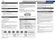
Determine Location for Concrete Pad and Operator
Refer to the illustration to determine the measurements and location of the concrete pad.
Inside
Outside Inside
Outside
A
F
B
C
D
10"
(25.4 cm)
DISTANCE
E
Long Arm Section
Short Arm Section
Concrete Pad
Gate Hinge Center
NOTE: There should only
be a maximum of
4" (10.2 cm) from the
center of the hinge to the
edge of the post or
column. If the distance is
greater than 4" (10.2 cm),
entrapment protection for
this area is required.
D MINUS 10"
(25.4 cm)
Dimension ( ) thru ( ) are from the center of one pivot point to the center of another pivot point.A E
Suggestion: The dimensions between the gate and the concrete pad is always 10 inches (25.4 cm) less than the dimension D.
Example: D = 42" (106.7 cm), if the dimensions between the gate and the concrete pad is 32" (81.3 cm).
Chart LA
Requires less clearance between gate and wall.
GATE LENGTH A B C D E F DISTANCE
22 ft.
2,500 lbs.max. 88" (2.24 m) 62.5" (1.58 m) 57.5" (1.46 m) 71" (1.80 m) 11" (27.9 cm) 3" (7.6 cm) 70" (1.78 m)
20 ft.
2,750 lbs. max. 80" (2.03 m) 58.25" (1.48 m) 52.25" (1.33 m) 65.5" (1.66 m) 11" (27.9 cm) 3" (7.6 cm) 65.75" (1.67 m)
18 ft,
3,250 lbs. max. 72" (1.83 m) 53" (1.35 m) 47" (1.19 m) 58.5" (1.49 m) 11" (27.9 cm) 3" (7.6 cm) 60.5" (1.54 m)
16 ft.
3,750 lbs. max. 64" (1.63 m) 48.25" (1.23 m) 41.75" (1.06 m) 52.5" (1.33 m) 11" (27.9 cm) 3" (7.6 cm) 55.75" (1.42 m)
14 ft.
4,500 lbs. max. 56" (1.42 m) 44.75" (1.14 m) 37.25" (.95 m) 50" (1.27 m) 11" (27.9 cm) 3" (7.6 cm) 52.25" (1.33 m)