Salus TRV28RFM Manual
Salus
Smart hjem
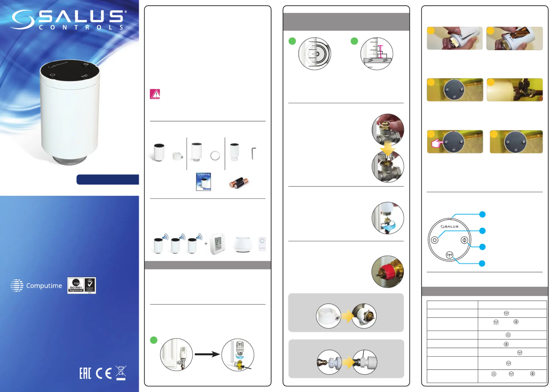
TRV28RFM
| Mærke: | Salus |
| Kategori: | Smart hjem |
| Model: | TRV28RFM |
Har du brug for hjælp?
Hvis du har brug for hjælp til Salus TRV28RFM stil et spørgsmål nedenfor, og andre brugere vil svare dig
Smart hjem Salus Manualer
1 Oktober 2025
1 Oktober 2025
23 Juli 2025
23 Juli 2025
22 Juli 2025
22 Juli 2025
22 Juli 2025
22 Juli 2025
22 Juli 2025

19 September 2024
Smart hjem Manualer
- Brennenstuhl
- JANDY
- TP-Link
- Tripp Lite
- Totolink
- Philips
- DoorBird
- Ikea
- Qnect
- Blebox
- SwitchBot
- Airthings
- Blaupunkt
- Digi
- MDT
Nyeste Smart hjem Manualer

22 December 2025

22 December 2025

22 December 2025

2 December 2025

2 December 2025

20 November 2025
15 November 2025
15 November 2025
14 November 2025
7 November 2025