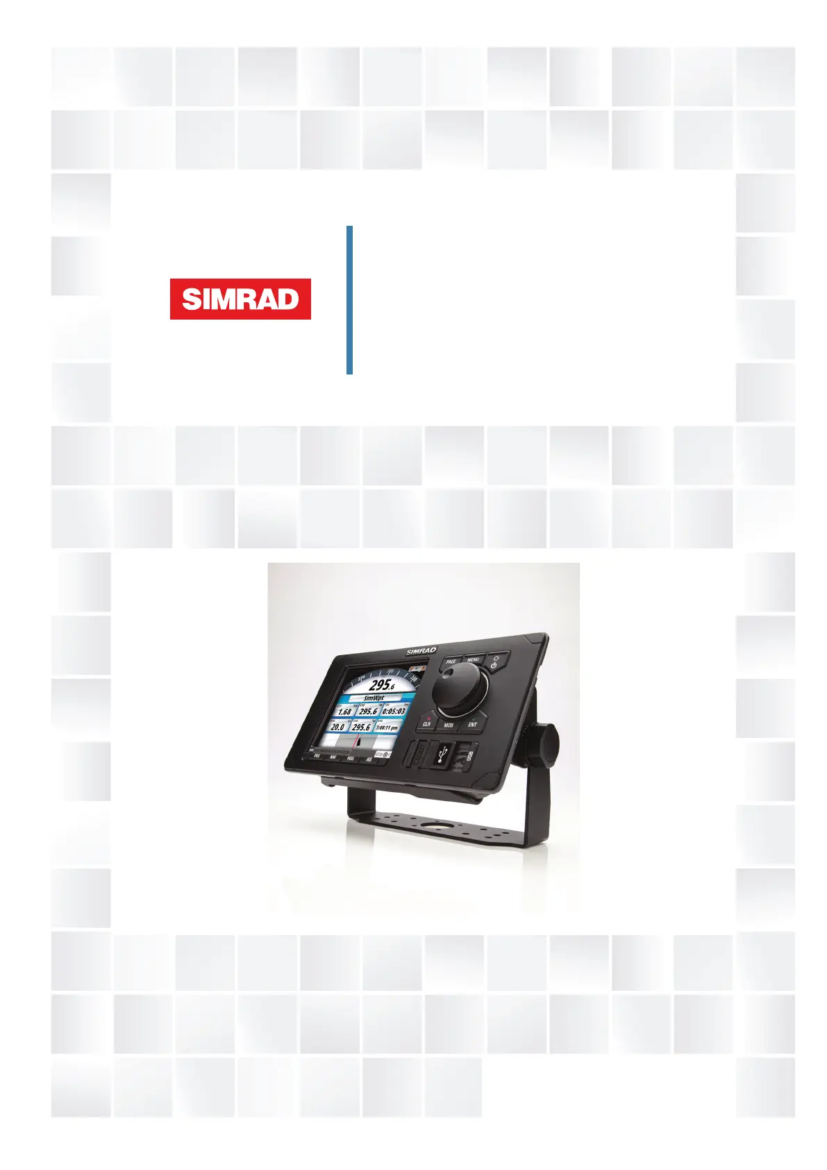
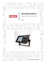
Simrad MX612 Manual


Læs gratis den danske manual til Simrad MX612 (4 sider) i kategorien Ikke kategoriseret. Denne vejledning er vurderet som hjælpsom af 22 personer og har en gennemsnitlig bedømmelse på 4.9 stjerner ud af 11.5 anmeldelser. Har du et spørgsmål om Simrad MX612, eller vil du spørge andre brugere om produktet?

Side 1/4
| 1
RF40 Rudder Feedback unit
Installation guide
The RF40 is a resistive rudder feedback unit, suitable for autopilot systems with a
NAC-1 or NAC-2 autopilot computer.
¼Note: The RF40 can not be used with the NAC-3 autopilot computer.
The RF40 might also be used with autopilot computers that have analog rudder
feedback input.
¼Note: Do not remove the transmitter lever from the feedback unit.
¼Note: The unit is factory adjusted and requires no further adjustment at
installation than described below.
Mounting location
The RF40 unit ( ) mounts close to the rudder, and is mechanically linked to the A
rudder tiller arm ( ) or rudder quadrant.B
Select a mounting location for the RF40 unit according to the illustration
X1 = X2: min 150 mm (5.9”), max 345 mm (13.6)
Y1 = Y2: min 44 mm (1.7”), max 130 mm (5.1)
X2
X1
Y1 Y2
X1 = X2
Y1 = Y2
A
B
2 |
Installation
The RF40 lever ( ) has two slots for the transmitter link ( ). The slots enable C D
maximum exibility to provide the 1:1 mechanical linkage relationship.
D
E
E
C
B
Y1 Y2
1. Turn the helm to set the rudder tiller arm ( ) to approximate center positionB
2. Mount the RF40 unit to a suitable platform
If required:
-add blocking material under the RF40 to adjust the height of the
transmitter lever to be level with the rudder tiller arm
-cut the length of the transmitter rod (D) to move the feedback unit closer
to the rudder post
3. Rotate the RF40 lever to center position
Ethe marks ( ) on unit and on the lever should be aligned
4. Rotate the RF40 unit so that the rudder lever is parallel with the rudder tiller arm
5. Set the transmitter link to the inner limit of the outer slot if possible
6. Drill and tap the rudder tiller arm so that the Y2 dimension is equal to the Y1
dimension
7. Attach the ball joint to the tiller arm, and connect the transmitter rod to the ball
joint at the rudder tiller arm
8. Tighten the mounting screws for both the RF40 and the transmitter rod ball
joint.
9. Observe the feedback unit while someone turns the helm through the complete
rudder travel hard-over to hard-over, and verify that the mechanical linkage
moves freely.


Produkt Specifikationer

Mærke: Simrad
Kategori: Ikke kategoriseret
Model: MX612

Har du brug for hjælp?

Hvis du har brug for hjælp til Simrad MX612 stil et spørgsmål nedenfor, og andre brugere vil svare dig