Simrad RF70N Manual


Læs gratis den danske manual til Simrad RF70N (2 sider) i kategorien Ikke kategoriseret. Denne vejledning er vurderet som hjælpsom af 3 personer og har en gennemsnitlig bedømmelse på 4.6 stjerner ud af 2 anmeldelser. Har du et spørgsmål om Simrad RF70N, eller vil du spørge andre brugere om produktet?

Side 1/2
Instructions
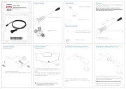
RF70N Rudder Feedback
RF70N Mounting
General
The RF70N is designed for electrical
connection to any NMEA 2000 network with
Micro-C connector backbone. The angle of
rotation is transmitted over the network.
Installation
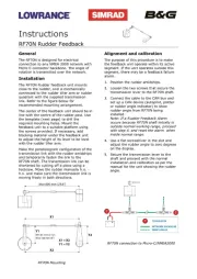
The RF70N Rudder feedback unit mounts
close to the rudder, and is mechanically
connected to the rudder tiller arm or rudder
quadrant with the supplied transmission
link. Refer to the figure below for
recommended mounting arrangement.
The center of the feedback unit should be in
line with the centre of the rudder post. Use
the template (next page) to drill the
required mounting holes. Mount the
feedback unit to a suitable platform using
the screws provided. If necessary, add
blocking material under the feedback unit
to adjust the height of its lever to be level
with the rudder tiller arm.
Make the parallelogram configuration of the
transmission link with the rudder amidships
and temporarily fasten the link to the
RF70N shaft. The transmission link can be
shortened by cutting off a piece using a
hacksaw. Move the rudder manually h.o. -
h.o. and make sure the transmission link is
moving freely in both directions.
Alignment and calibration
The purpose of this procedure is to make
the feedback unit operate within its active
segment. If the unit operates outside this
segment, there may be a feedback failure
alarm.
1. Position the rudder amidships.
2. Loosen the two screws that secure the
transmission lever to the RF70N shaft.
3. Connect the cable to the CAN bus and
set up a CAN device (autopilot, plotter
or rudder angle indicator) to show
rudder angle from RF70N being
installed.
Note: If a Rudder Feedback Alarm
occurs because RF70N shaft initially is
outside normal working range, proceed
with step 4. and reset the alarm when
inside normal range.
4. Use a flat screwdriver in the slot and
adjust the rudder angle to zero degrees
on the display.
5. Secure the transmission lever to the
shaft and proceed with the normal
installation and calibration as per the
manual for the unit showing the rudder
angle.
RF70N connection to Micro-C/NMEA2000


Produkt Specifikationer

Mærke: Simrad
Kategori: Ikke kategoriseret
Model: RF70N

Har du brug for hjælp?

Hvis du har brug for hjælp til Simrad RF70N stil et spørgsmål nedenfor, og andre brugere vil svare dig


Ikke kategoriseret Simrad Manualer
Simrad

Simrad RF70N Manual

31 Oktober 2025
Simrad

Simrad NAC-1 Manual

23 August 2025
Simrad

Simrad IDS Display Manual

22 August 2025
Simrad

Simrad NAC-3 Manual

22 August 2025
Simrad

Simrad SD10 Manual

22 August 2025
Simrad

Simrad GS70 Manual

22 August 2025
Simrad

Simrad MX610 Manual

22 August 2025
Simrad

Simrad RS40-B Manual

22 August 2025

Ikke kategoriseret Manualer

Nyeste Ikke kategoriseret Manualer