Simrad Recon Head Cover Manual

Simrad Ikke kategoriseret Recon Head Cover

Læs gratis den danske manual til Simrad Recon Head Cover (3 sider) i kategorien Ikke kategoriseret. Denne vejledning er vurderet som hjælpsom af 3 personer og har en gennemsnitlig bedømmelse på 4.7 stjerner ud af 2 anmeldelser. Har du et spørgsmål om Simrad Recon Head Cover, eller vil du spørge andre brugere om produktet?

Side 1/3
Recon
Head Cover GPS/PCB Assembly
Installation Guide: EN
Document version: 001
WARNING: This product must be installed in
accordance with the instructions provided. Failure to do
so could result in personal injury, damage to your vessel
WARNING: Performing service or maintenance
without rst disconnecting the battery can cause product
damage, personal injury, or death due to re, explosion,
electrical shock, or unexpected motor starting. Always
disconnect the battery cables from the battery before
maintaining, servicing, installing, or removing motor
components.
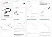
In the box
1x head cover GPS/PCB assembly
5x #6 screws
Tools needed
#2 Phillips screwdriver
Torque wrench
Installation
To remove the existing head cover GPS/PCB assembly:
¼Note: This procedure can be completed while the trolling
motor is in either the stowed or deployed position.
1 Disconnect the trolling motor power cable from the
battery (or unplug the power cable if using a plug and
receptacle).
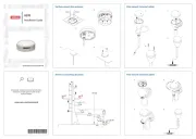
2 Using a #2 Phillips screwdriver, remove the ve screws
( ) from the underside of the head base.A
A
A
3 Disconnect the head-to-mount communication cable
(larger cable with blue, 5-pin connector) by turning the
black locking collar ( ) a 1/4 turn. B
4 Disconnect the head-to-lower unit communication cable
(smaller cable with black, 4-pin connector) by turning
the connector ( ) until it loosens.C
B
C
5 Separate the head cover from its base.
To attach the new head cover GPS/PCB assembly:
6 Connect the head-to-mount communication cable by
aligning the arrows on the connectors, sliding together
and turning the black locking collar a 1/4 turn.
7 Connect the head-to-lower unit communication cable by
aligning the white dots and arrows on the connectors,
sliding together and turning until tight.
8 Position the head cover over the head base and ensure
all cables are tucked inside.
¼Note: The head cover can only go one way.
9 Secure using ve new #6 screws (supplied), and tighten
to torque 1.36 Nm (12 in-lb).
Update software
Wait for software versions to match
When the trolling motor is powered on after any new board
is installed, the GPS/PCB assembly in the head of the
trolling motor automatically pushes its current software
to the mount controller board (even if the mount controller
board has been loaded with a more recent version of the
software).
Wait for this to complete before pushing the latest available
software to the trolling motor.
Update the trolling motor to the latest available
software
After installing any new circuit board, you should install the
latest available software on the trolling motor.
For instructions on how to update the trolling motor
software, refer to the Recon operator manual.
Before updating:
Stow the trolling motor.
Pair and connect any foot pedals and remote controls
you want to use, so they receive the same software
update.
When updates are complete, power cycle the trolling motor
then wait 60 seconds before starting calibrations.
Calibration
After youve replaced the head cover GPS/PCB assembly
and updated the software, you need to re-calibrate the
trolling motors centerline, bow offset, and compass, and
power cycle the trolling motor.
Calibrate the centerline
¼Note: Calibrating the trolling motors centerline is
currently achieved using an Advanced Wireless Foot
Pedal. It will be supported in future releases of the
FreeSteer Joystick Remote and the Lowrance and
Simrad
®
mobile apps.
Foot pedal
1 Deploy the trolling motor to where the lower unit can be
seen and is able to rotate 360° without obstruction. For
best visibility, slide the depth collar down so the lower
unit is close to the mount.
¼Note: The motor does not need to be in the water for this
calibration - it just needs to be deployed and free of any
obstructions when rotating the lower unit.
2 Power on the trolling motor and make sure it is
connected to the Advanced Wireless foot pedal.
3 To enter service mode, press and hold the and keys
on the foot pedal simultaneously until the trolling motor
beeps twice and the LEDs on the mount start flashing.
4 To enter centerline calibration mode, press and hold the
and keys on the foot pedal simultaneously until the
trolling motor beeps twice.
5 ABy hand, move the lower unit nosecone ( ) until it is
parallel to the center of the steering transmission ( ), B
then press and hold the key on the foot pedal until the
motor beeps twice.
B
A


Produkt Specifikationer

Mærke: Simrad
Kategori: Ikke kategoriseret
Model: Recon Head Cover

Har du brug for hjælp?

Hvis du har brug for hjælp til Simrad Recon Head Cover stil et spørgsmål nedenfor, og andre brugere vil svare dig