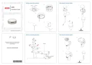
Simrad RECON UI Cover Manual

Simrad Ikke kategoriseret RECON UI Cover

Læs gratis den danske manual til Simrad RECON UI Cover (2 sider) i kategorien Ikke kategoriseret. Denne vejledning er vurderet som hjælpsom af 3 personer og har en gennemsnitlig bedømmelse på 4.6 stjerner ud af 2 anmeldelser. Har du et spørgsmål om Simrad RECON UI Cover, eller vil du spørge andre brugere om produktet?

Side 1/2
Recon
Mount UI Cover
Installation Guide: EN
Document version: 001
WARNING: This product must be installed in
accordance with the instructions provided. Failure to do
so could result in personal injury, damage to your vessel
WARNING: Performing service or maintenance
without rst disconnecting the battery can cause product
damage, personal injury, or death due to re, explosion,
electrical shock, or unexpected motor starting. Always
disconnect the battery cables from the battery before
maintaining, servicing, installing, or removing motor
components.
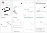
In the box
1x Recon mount UI cover
2x #6 x 3/8, pan, T15 Torx
®
, SS screws
2x M3-0.5 x 8, flange, hex, SS screw
Tools needed
#2 Phillips screwdriver
5/32 in Allen key
2 mm Allen key
T15 Torx
®
screwdriver
Torque wrench
Introduction
The mount user interface cover (UI cover) contains the
circuit boards for the keys and LEDs on the mount. The
UI cover also protects the main circuit board and the
connections inside the trolling motor mount.
Removal
To remove the existing mount UI cover:
1 Disconnect the trolling motor power cable from the
battery (or unplug the power cable if using a plug and
receptacle).
2 While your trolling motor is stowed or deployed, use a
#2 Phillips screwdriver to loosen the side plate screws
on both sides of the mount ( ).A
¼Note: The screws are retained by washers.
A
3 Remove the side plates, taking care not to damage the
locating tabs as they leave their slots ( ).B
4 Deploy the trolling motor.
5 Use a 2 mm Allen key to remove the screw from both
sides of the UI cover ( ).C
6 Use a 5/32 in Allen key to loosen the two screws ( ) that D
secure the coil cable bracket 23 full rotations. These
screws have a blue thread-locking compound applied to
them. Ease the coil cable bracket ( ) outward from the E
mount.
E
7 Lift the UI cover upward to separate it from the mount.
WARNING: Do not lift the UI cover more than 30 cm
(~12 in) above the mount, to avoid damaging the ribbon
cable ( ) that remains connected to the mount.F
F
© 2025 Navico Group. All Rights Reserved. Navico Group is a division of Brunswick Corporation.
®
Reg. U.S. Pat. & Tm. Off, and common law marks. Visit www.navico.com/intellectual-property to
review the global trademark rights.
5 Ease the coil cable bracket ( ) into position so that the F
root of the coil cable is gripped between the mount UI
cover and the coil cable bracket. Use a 5/32 in Allen key
to tighten the two screws ( ) that secure the coil cable G
bracket. Tighten to torque 5.08 Nm (45 in-lb).
6 Use a 2 mm Allen key to install two M3-0.5 x 8 flange
screws ( , supplied) into the sides of the UI cover. H
Tighten to torque 0.35 Nm (3 in-lb).
F
7 IInsert the front locating tab ( ) of the port side plate into
its locating slot on the port side of the mount.
8 JGently apply pressure below the other locating tab ( )
and flex it into its locating slot.
9 Guide the strain relief ( ) around the base of the coil K
cable.
10 Fasten the side plate screws and tighten to torque
1.69Nm (15 in-lb).
11 To replace starboard side plate on mount, insert the
locating tabs into their locating slots and gently attach
the plate.
12 Fasten the side plate screws and tighten to torque
1.69Nm (15 in-lb).
8 Rest the UI cover beside the mount, open side upward.
9 Use a T15 Torx
®
screwdriver to remove the two screws
( ) that secure the LED assembly ( ) to the inside of the G H
UI cover.
¼Note: The ribbon cable (F) remains attached to the LED
assembly and to the mount circuit board assembly.
G G
H
F
Installation
To attach the new mount UI cover:
1 AMake sure the ribbon cable ( ) from the mount circuit
board is not twisted. Position the LED assembly ( ) on B
the inside of the mount UI cover by aligning the screw
holes.
2 Use a T15 Torx
®
bit or screwdriver to install two #6 x
3/8 pan head screws ( , supplied. These 3/8 inch-length C
screws are the shorter T15 Torx
®
screws supplied in the
service kit). Tighten to torque 0.68 Nm (6 in-lb).
C C
B
A
3 Inside the mount, check the grommet on the
transmission cable (D) is tted into the cable retainer (E).
D
E
4 Lower the mount UI cover into position. Guide its front
face to t over the cable retainer and grommet.


Produkt Specifikationer

Mærke: Simrad
Kategori: Ikke kategoriseret
Model: RECON UI Cover

Har du brug for hjælp?

Hvis du har brug for hjælp til Simrad RECON UI Cover stil et spørgsmål nedenfor, og andre brugere vil svare dig