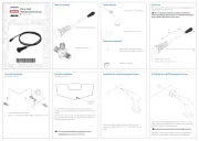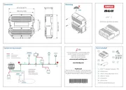
The RF25N is designed for connection to
any NMEA 2000 network with Micro-C
connector backbone. It is equipped with
transmission link and 5.5 m (18 feet) of
cable with connector. It transforms the
angular travel of the rudder to a digital
signal and broadcast it to compatible
devices connected to the NMEA2000
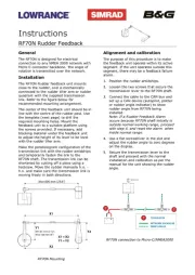
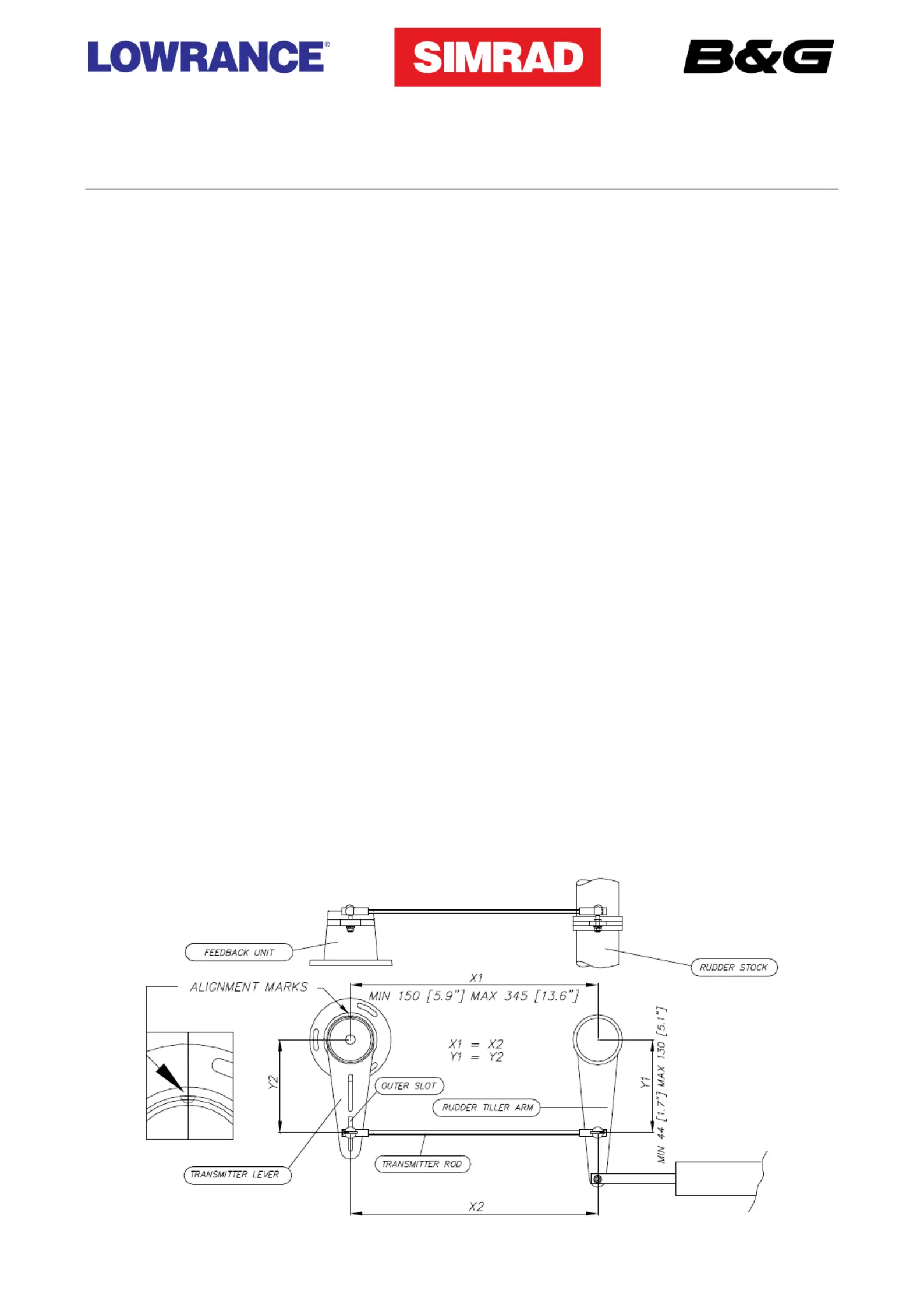
The RF25N Rudder feedback unit mounts
close to the rudder, and is mechanically
linked to the rudder tiller arm or rudder
quadrant. Refer to the figure below for
recommended mounting arrangement.
Do not remove the transmitter lever from
the feedback unit. The unit is factory
adjusted and need no further adjustment at
installation than described below.
Turn the helm to set the rudder tiller arm to
approximate centre position.
Set the mounting location to be in
accordance with the figure. The centre of
the feedback unit should be in line with the
centre of the rudder post. Mount the
feedback unit to a suitable platform using
the screws provided. If necessary, add
blocking material under the feedback unit
to adjust the height of the transmitter lever
to be level with the rudder tiller arm.
Due to space limitations, it may be neces-
sary to cut the length of the transmitter rod
to move the feedback unit closer to the
Rotate the feedback transmitter lever to
centre position. (Use the alignment mark to
line up the transmitter lever to be opposite
the cable entry into the feedback).
Carefully observe the alignment marks. A
rudder feedback alarm may be the result if
the alignment instructions are neglected.
Note that the transmitter lever has two
slots for the transmitter link. The slots
enable maximum flexibility to provide the
1:1 mechanical linkage relationship. As a
starting point, set the transmitter rod to the
inner limit of the outer slot if possible. Drill
and tap the rudder tiller arm so that the Y1
dimension is equal to the Y2 dimension
(Use 4.2 mm drill and 5 mm tap). Attach
the ball joint to the tiller arm, and connect
the transmitter rod to the ball joint at the
Tighten the mounting screws for both the
feedback unit and the transmitter rod ball
Observe the feedback unit while someone
turns the helm wheel through the complete
rudder travel H.O. to H.O. and verify that
the mechanical linkage moves freely.