電気製品は、安全のための注意事項を守らないと、火災や人身事故にな
この設置説明書には、事故を防ぐための重要な注意事項と製品の取り扱いかたを示し
てあります。この設置説明書をよくお読みのうえ、製品を安全にお使いください。お読
みになったあとは、いつでも見られるところに必ず保管してください。
85.7 (3 3/8)
83.5 (2 9/32)
次の機種は、機能が同等であるため、ユーザーガイドの本文中は機種名を省略し
カメラを安全に使うための注意事項が記載されています。必ずお読みください。
この設置説明書には、カメラ本体の各部の名称や設置、接続方法が記載されてい
設置説明書にしたがってカメラを正しく設置、接続したあと、ユーザーガイドを
が収納されています。また、セットアップ方法についての情報が
ユーザーガイドやアプリケーションガイドをご覧になりたい場合は、
http://www.sony.net/ipela/snc
がインストールされたコンピューターで、各ガイドを閲覧できま
が破損または紛失した場合は、お買い上げ店またはソニーのサービス
Adobe Systems Incorporated
パイプを接続します。接続口はカメラ本体の側面にあります。出荷時は側面の
が付いています。必要に応じてカバーを付け換えて、パイプを取
屋内配線をするときに、カメラと、天井や壁の間にケーブルがはさみ込まれない
ようご注意ください。ケーブルがはさみ込まれると、断線による火災や感電の原
レンズの撮影範囲(ズーム)、フォーカス調整時に使用します。スイッチを倒す方
(ニア):近くのものにフォーカス(焦点)を合わせます。
スイッチ中央を長押しすると、自動的にフォーカスを合わせま
取り付ける際、取り付けネジはしっかり締めてください。
ビデオモニターの映像入力端子と接続します。カメラおよびレンズの調整を行
うとき、本機で撮っている画像をビデオモニター画面上で見ることができます。
ネジをゆるめてからカメラブロックを撮影したい方向に向け、そのあと締めて固
ドームケースを開けたときにカメラ本体からドームケースが脱落するのを防ぎ
接続について詳しくは、電源供給装置の取扱説明書をご覧ください。
*PoE: Power over Ethernet
ドームカバーはポリカーボネート製です。本体との接合部には防水用ゴムが付
カメラに電源が供給されると、カメラ内部でシステムチェックを行います。
正常に動作している場合はこのインジケーターが点灯します。
内蔵のヒーターが正常に動作している場合、点灯します。
ネットワークに接続されているときは点灯、または点滅します。ネットワークに
先の細い物でこのスイッチを押しながら電源を供給すると、工場出荷時
スイッチを設定した後は、カメラを再起動してください。
カメラを設置するときは、必ずアースを取ってください。
本機の名称や、電気関係の定格情報が記載されています。
出荷時、すべての付属ケーブルはカメラに接続済みです。
ご使用環境に合わせてケーブルの接続、配線を変更する場合は、下記の手順をご
ケーブルを側面から引き出すときは、「側面の接続口を使う場合」をご覧く
でない場合は、接続口(底面)を防水処理してください。
防水作業が必要な場合は、「カメラ設置時の注意事項」(裏面)を必ずご覧くださ
ケーブルは強く引かないでください。端子からはずれる恐れがあります。
接続口(底面)が汚れていると、接続口カバーがうまく取り付けられず、カメラ
本体に雨などが入り、故障の原因になります。柔らかい布などで汚れを拭き取
雨などを防ぐため、パイプやカバーを取り付けたあとに、シリコンシーラント
接続口(底面)に接続口カバーを取り付けるとき、ホルダープレートとケーブル
カメラを設置または取り外すときは、接続口カバーとナット(
壁や天井など高所へ設置する際は、専門の工事業者に依頼してください。
高所への設置は、設置部および使用する取り付け部材(付属品を除く)が
以上の重量に充分耐えられる強度があることをお確かめの上、確実に取り付け
てください。充分な強度がないと落下して大けがの原因となります。
落下事故防止のため、付属のワイヤーロープを必ず取り付けてください。
てください。また、使用状況に応じて点検の間隔を短くしてください。
カメラの撮影方向を決めてから、付属のテンプレートを使って配線用の穴(φ
壁にネジ止めします。設置する場所や材質により、使用するネジ類が異なります。
コンクリート壁の場合:ドライビット、またはプラグボルトで固定してください。
ジャンクションボックスの場合:ジャンクションボックスのネジ穴に合ったネ
設置する場所や材質により、適切な取り付けネジを使用してください。適切な取
り付けネジを使用しないと落下して大けがの原因になります。
ドームケースを手前に持ち上げて外す。(ネジが引っ掛かるときは、ネジを
使用するネジについては、「取り付けネジについて」をご覧ください。
付属のワイヤーロープをカメラと天井、または壁に取り付ける。
カメラを壁面に設置するときは、ワイヤーロープ用スリットにワイヤー
ネジには脱落防止機構があります。ネジをカメラのネジ穴に差し込んだ状態
所に差し込み、カメラ本体を時計方向に回して、位置決めピンをホルダーの穴
天井や壁に取り付けネジを使えない場合や、カメラ本体を目立たせたくない場合
天井埋め込み金具でカメラを取り付けるときは、天井埋め込み金具の左右金具の
の位置に固定してお使いください。詳しくは、天井埋め込み金具
Before operating the unit, please read this manual thoroughly and retain it for
SNC-EM602RC/EM632RC’s functions are the same as the SNC-EM602R/EM632R.
So the model names are written simply in the User’s Guide.
SNC-EM632RC is described as E Series or SNC-EM632R.
SNC-EM602RC is described as E Series or SNC-EM602R.
Safety Regulations (supplied)
The Safety Regulations describes the secure usage of camera. Be sure to read it.
Installation Manual (this document)
This Installation Manual describes the names and functions of parts and controls
of the Network Camera, gives connection examples and explains how to set up
the camera. Be sure to read the Installation Manual before operating.
SNC easy IP setup Guide (stored in the CD-ROM)
User’s Guide/Application Guide (Web)
The User’s Guide describes how to set up the camera and how to control the
camera via a Web browser.
After installing and connecting the camera correctly, operate referring to this
The supplied CD-ROM includes the setup program for assigning an IP address.
The information for how to set up an IP address is also included in the disc in PDF
User’s Guide and Application Guide can be downloaded from the disc, or the
http://www.sony.net/ipela/snc
The manual can be read on a computer with Adobe Reader installed.
You can download Adobe Reader free from the Adobe website.
1 Open the index.html file in the CD-ROM.
2 Select and click on the manual that you want to read.
If you have lost or damaged the CD-ROM, you can purchase a new one from your
Sony dealer or Sony service counter.
Adobe and Acrobat Reader are trademarks of Adobe Systems Incorporated in the
United States and/or other countries.
Assign the IP address using the setup program in the supplied CD-ROM.
For details on how to set up the IP address, see SNC easy IP Setup Guide.
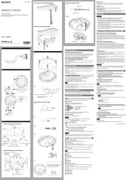
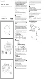
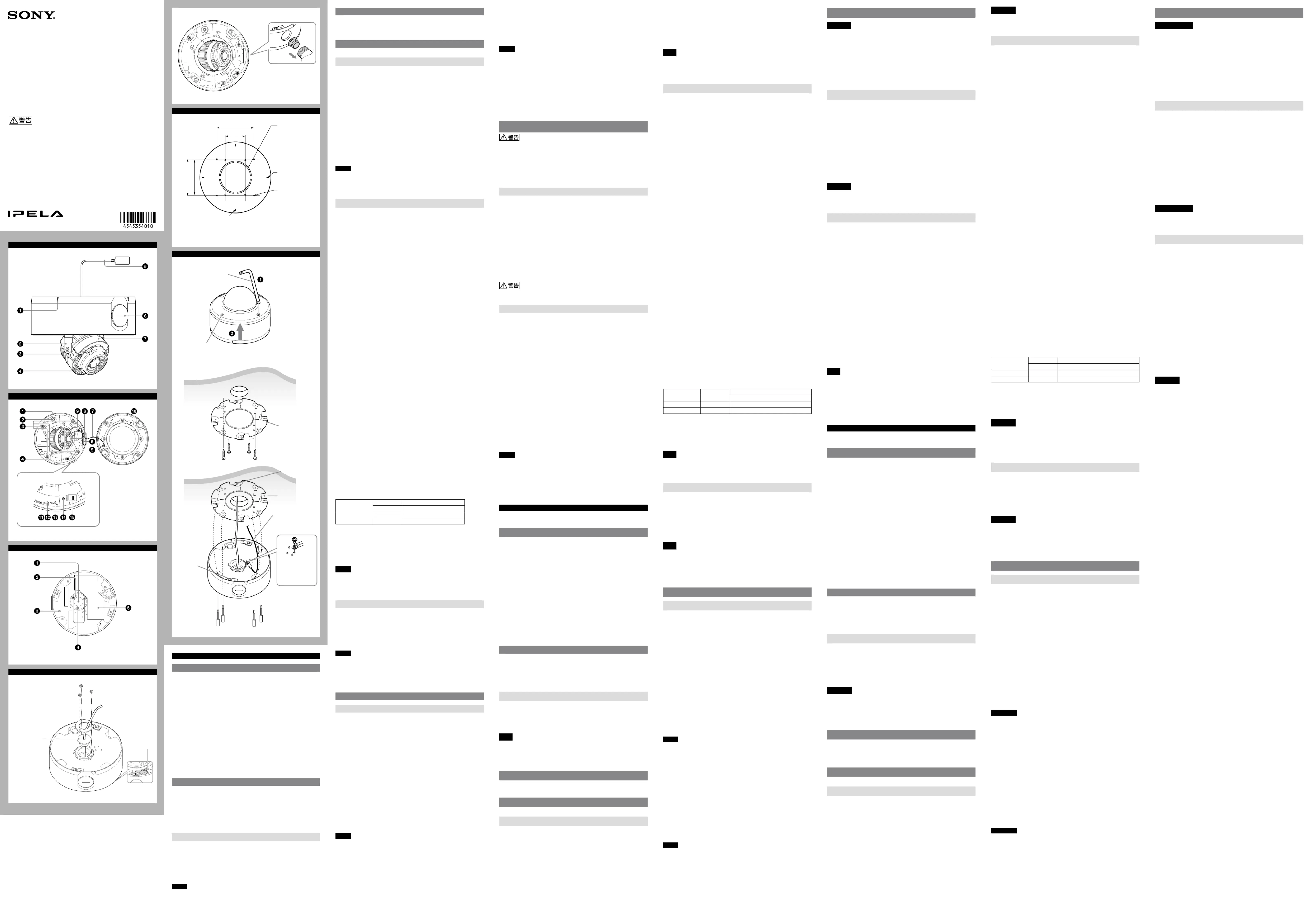
Location and Function of Part
The figure shows the camera without the dome casing.
Feed the wire rope through this.
For details, see “Installing the Camera.”
LAN cable (RJ-45) (supplied and connected to the camera at the
Connect this cable to a hub or computer on the 10BASE-T or 100BASE-TX
network using a commercially available network cable (UTP, category 5).
inches NPT or M27 (2.0 mm (
pitched, hole diameter ø27 mm (1
Connect a pipe to this hole. There is a conduit hole on the side of the camera
unit. The conduit hole cover is installed in the side conduit hole at the factory.
Remove the cover as needed and connect the pipe to the hole.
An M25 cable gland can be connected to the hole by removing the nut inside the
Take care not to trap the cables between the camera and the ceiling or the wall. If
the cable is trapped, it may cause a fire or electric shock due to breaking.
Use this switch to adjust lens’ zoom and focus. Slide the switch lever to select the
[N] NEAR: Focus on a nearby subject
[F] FAR: Focus on a distant subject
Hold down the center of the ZOOM/FOCUS switch for a moment to focus
Camera unit mounting screws (four positions)
Make sure to tighten the screws securely when installing the camera.
Connect this jack to a video input connector of a video monitor. You can adjust
the camera or lens while looking at the image on the video monitor. After
adjusting the camera or lens, disconnect the cable.
Camera block fixing screws (tilt) (two positions)
Firstly, loosen the screws and point the camera block in the desired direction,
then tighten the screws to secure in place.
¾ inches NPT or M27 (2.0 mm (
This cord prevents the dome casing from falling off the unit.
Indicates the image direction.
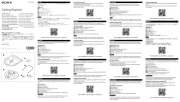
Connect a commercially available network cable (UTP, category 5) to
communicate with a network or PoE/PoE+* system.
For details on connection, see the Instruction Manual of the power supply
(*PoE/PoE+ stands for Power over Ethernet. It is pursuant to IEEE802.3at.)
The dome cover is made of polycarbonate. A waterproof rubber gasket is
provided on the joint surface to the unit.
When the power is supplied to the camera, the camera starts checking the
system. If the system is normal, this indicator lights up.
The indicator lights up in green when the built-in heater is working normally.
NETWORK indicator (Green/Orange)
The indicator lights up or flashes when the camera is connected to the network.
The indicator is off when the camera is not connected to the network.
To reset the camera to the factory default settings, hold down this switch with a
point and supply the power to the camera.
Mode setting DIP switches
DIP switch function/settings
PoE+(at) -40°C to +50°C (-40°F to +122°F)
PoE(af) -30°C to +50°C (-22°F to +122°F)
1 Video (NTSC/PAL) switch (Initial setting: NTSC)
Switches the video output.
After setting the switch, reboot the camera unit.
2 PoE Power switch (Initial setting: PoE)
Switches the PoE+/PoE depending on the used PoE hub.
When power is supplied by IEEE802.3at (PoE+) equipment, if the PoE Power
switch is set to PoE, the range of activation and operating temperature is limited.
When power is supplied by IEEE802.3af (PoE) equipment, if the PoE Power switch
is set to PoE+, the camera will not work properly.
LAN cable holder (supplied and connected to the camera at the
Packing for waterproofing the cables.
Ground the camera when you install it.
Use the supplied Screws (M4 × 8)
Holder plate fixing screws (three positions)
Shows the name of this camera and its electric rating.
Change connections and cable wiring
All the supplied cables are connected to the camera at the factory.
To change connections and cable wiring to suit your requirements, perform the
When you route the cables from the side of the camera unit, see “Connecting to
a) If you use the camera with its factory setting
The preparation is completed.
b) If you use your own LAN cable
1 Loosen the four screws of the dome casing using the supplied wrench and
2Loosen the three holder plate fixing screws on the bottom to remove the
holder plate and LAN cable holder.
3 Disconnect the LAN cable (connected at the factory) from the LAN port and
remove it from the LAN cable holder.
4 Insert your LAN cable through the hole of the LAN cable holder.
5 Insert the LAN cable through the bottom hole and adjust the length of the
LAN cable from the hole to the LAN port.
6 Connect the LAN cable to the LAN port.
7 Attach the removed holder plate to the bottom hole with the three holder
For case b), keep your LAN cable diameter
inches). Otherwise, waterproof the bottom hole.
If you need to waterproof the camera, see “Important precautions” overleaf.
Do not pull on any cables forcefully, as a connection may become loose.
c) Connecting to the side conduit hole
The LAN cable is connected to the camera through the bottom hole at the
factory. If you want to use the side conduit hole, perform the following steps:
1 Remove the conduit hole cover.
2 Loosen the three holder plate fixing screws on the bottom to remove the
holder plate and LAN cable holder.
3 Disconnect the LAN cable from the LAN port, and pull it out through the
4 Insert the LAN cable through the pipe, then through the supplied cable
holder (for conduit), and finally through the side conduit hole. ( -c-1)
5 Connect the LAN cable to the LAN port.
6 Screw the removed conduit hole cover into the bottom hole.
If the bottom hole is dirty, the conduit hole cover cannot be fixed firmly. In this
case, moisture may leak into the casing and this may cause a malfunction.
Wipe off the dust with a soft cloth, and fix the conduit hole cover firmly.
Cover the joint part of the pipe/cover with silicon sealant, etc. to prevent
moisture from getting inside the casing.
The holder plate and the cable holder are not necessary when you attach the
conduit hole cover to the bottom hole.
Be careful not to drop the conduit hole cover and nut (
For details on using the supplied cable holder (for conduit), see “Important
If you attach the camera in the height such as the wall or the ceiling, etc.,
entrust the installation to an experienced contractor or installer.
If you install the camera at a height, ensure that the installation location and
its material are strong enough to withstand a weight of 15 kg (33 lb 11 oz) or
more, and then install the camera securely. If the ceiling is not strong enough,
the camera may fall and cause serious injury.
To prevent the camera from falling, make sure to attach the supplied wire rope.
If you attach the camera to the ceiling, check periodically, at least once a year,
to ensure that the connection has not loosened. If conditions warrant, make
this periodic check more frequently.
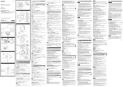
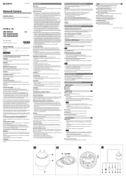
Deciding the Installation Location of the Camera
After deciding the direction in which the camera will shoot, make the required
inches)) for the connecting cables using the supplied
template. Then decide the four mounting hole positions to install the bracket.
The supplied bracket is provided with eight ø4.5 mm (
holes. Install the bracket on a ceiling or wall with screws through four mounting
inches)-pitched holes or four 85.7 mm (3
pitched holes. The required mounting screws differ depending on the installation
location and its material. (Mounting screws are not supplied.)
Steel wall or ceiling: Use M4 bolts and nuts.
Wooden wall or ceiling: Use M4 tapping screws. The panel thickness must be
Concrete wall: Use anchors, bolts and plugs suitable for concrete walls.
Junction box: Use screws to match the holes on the junction box.
The required mounting screws differ depending on the installation location and
its material. If you do not secure the camera with the appropriate mounting
screws, the camera may fall off.
Loosen the screws with the wrench (supplied).
Pull up and remove the dome casing. When the screw catches on the
screw hole, pull up the screw.
2 Install the supplied bracket on the ceiling or wall.
Refer to “Mounting screws” for screws to be used.
3 Fix the supplied wire rope to the camera unit and the ceiling or wall.
Fix the wire rope with the supplied Screw M4
wire rope on the bottom of the camera unit.
Fix the wire rope to the ceiling or wall.
When you install the camera on a wall, feed the cables through one of the
4 Attach the camera unit to the bracket with the supplied four camera unit
The screws have a fall-prevention mechanism. The screws inserted into the
screw holes of the camera unit do not fall even if you turn the camera unit
Insert the two holders to any two of the four grooves on the bracket.
Turn the camera clockwise until the locating pins snap to the holes on the
holders. Then the four camera installation holes will align the projections on
the bracket accordingly. There are four projections with an angle of
90 degrees, so you can select one of four directions.
Then tighten the four camera unit mounting screws to attach the camera unit
to the bracket through the camera installation holes.
If you cannot use screws on a ceiling or wall, or if you want to make the camera
less conspicuous, use the YT-ICB45 in-ceiling bracket (optional) with which you
can mount the camera on the ceiling.
For this model, install the camera to the position on the side brackets of
YT-ICB45. Refer to the Installation Instructions of YT-ICB45 for detail information.
Avant d’utiliser l’appareil, veuillez lire attentivement ce manuel et le conserver
Les fonctions du SNC-EM602RC/EM632RC sont identiques à celles du SNC-
C’est pour cette raison que les noms de modèle sont simplement mentionnés
dans le Guide de l’utilisateur.
Le SNC-EM632RC est décrit en tant que Série E ou SNC-EM632R.
Le SNC-EM602RC est décrit en tant que Série E ou SNC-EM602R.
Règles de sécurité (fourni)
Le document Règles de sécurité décrit l’utilisation correcte de la caméra.
Manuel d’installation (le présent document)
Ce Manuel d’installation indique les noms et fonctions des pièces et commandes
de la Network Camera, fournit des exemples de raccordement et explique
comment installer la caméra. Lisez impérativement le Manuel d’installation avant
Guide de l’outil SNC easy IP setup (sur le CD-ROM)
Guide de l’utilisateur/Manuel d’application (Web)
Le Guide de l’utilisateur explique comment installer la caméra et commander
cette dernière via un navigateur Web.
Après avoir installé et raccordé la caméra, suivez les instructions de ce Guide de
Le CD-ROM fourni contient un programme d’attribution d’adresse IP. Le disque
contient également des informations sur la configuration d’une adresse IP au
Vous pouvez télécharger le Guide de l’utilisateur et le Manuel d’application à
partir du disque ou de l’adresse URL suivante :
http://www.sony.net/ipela/snc
Utilisation du manuel sur CD-ROM
Vous devez installer Adobe Reader sur votre ordinateur pour pouvoir lire ce
Vous pouvez télécharger Adobe Reader gratuitement depuis le site Web d’Adobe.
Ouvrez le fichier index.html situé sur le CD-ROM.
Sélectionnez le manuel que vous souhaitez lire, puis cliquez sur ce
Si vous avez perdu ou endommagé le CD-ROM, vous pouvez acheter un CD-ROM
de remplacement auprès de votre représentant Sony ou du service clientèle
Adobe et Acrobat Reader sont les marques de commerce d’Adobe Systems
Incorporated aux États-Unis et/ou dans d’autres pays.
Attribution de l’adresse IP
Attribuez l’adresse IP à l’aide du programme de configuration contenu sur le
Pour plus de détails sur la configuration de l’adresse IP, reportez-vous au Guide
de l’outil SNC easy IP setup.
Emplacement et fonctions des pièces
Le schéma montre la caméra dépourvue de logement dôme.
Faites passer le fil d’acier à travers.
Pour plus de détails, reportez-vous à la section « Installation de la caméra ».
Câble LAN (RJ-45) (fourni et raccordé à la caméra en usine)
Raccordez ce câble à un concentrateur ou à un ordinateur sur le réseau 10BASE-T
ou 100BASE-TX à l’aide d’un câble réseau (UTP, catégorie 5) disponible dans le
Trou du conduit latéral (
pouce NPT ou pas M27 (2,0 mm
pouce), diamètre du trou ø27 mm (1
Raccordez un conduit à ce trou. Il existe également un trou de conduit sur le côté
de la caméra. Le cache de l’orifice du conduit est monté en usine sur le trou du
conduit latéral. Si nécessaire, retirez le cache et raccordez le conduit à ce trou.
Un tuyau à bride M25 peut être raccordé à l’orifice en retirant l’écrou situé à
l’intérieur de la caméra.
Veillez à ne pas coincer les câbles entre la caméra et le plafond ou le mur. Si le
câble est coincé, une rupture peut causer un incendie ou un choc électrique.
Utilisez ce commutateur pour régler le zoom et la mise au point de l’objectif.
Faites glisser le levier de commutateur sur la fonction de votre choix.
[N] NEAR : mise au point sur un sujet proche
[F] FAR : mise au point sur un sujet éloigné
Maintenez le centre du commutateur ZOOM/FOCUS enfoncé pendant un
moment pour mettre au point automatiquement.
Vis de montage de caméra (quatre positions)
Assurez-vous de bien serrer les vis lors de l’installation de la caméra.
Branchez cette prise à un connecteur d’entrée vidéo d’un moniteur vidéo. Vous
pouvez régler la caméra ou l’objectif tout en regardant l’image sur le moniteur
vidéo. Débranchez le câble après avoir réglé la caméra ou l’objectif.
Vis de fixation du bloc de caméra (inclinaison) (deux positions)
Tout d’abord, desserrez les vis et orientez le bloc de caméra dans la direction de
votre choix, puis resserrez les vis pour le fixer.
Ce cordon évite la chute du logement de la caméra.
Indique la direction de l’image.
Raccordez un câble réseau disponible dans le commerce (UTP, catégorie 5) pour
communiquer avec un réseau ou un système PoE/PoE+*.
Pour plus de détails sur le raccordement, reportez-vous au Mode d’emploi de
l’équipement d’alimentation électrique.
(*PoE/PoE+ signifie Power over Ethernet. Cette technologie est conforme à la
Le logement dôme est en polycarbonate. Un joint en caoutchouc étanche à l’eau
est fourni sur la surface de joint de la caméra.
La caméra démarre une vérification du système lorsqu’elle reçoit une
alimentation électrique. Ce témoin s’allume si le système fonctionne
Ce témoin s’allume en vert lorsque la résistance intégrée fonctionne
Témoin NETWORK (vert/orange)
Ce témoin s’allume ou clignote lorsque la caméra est connectée au réseau. Le
témoin est éteint lorsque la caméra n’est pas connectée au réseau.
Commutateur de réinitialisation
Pour rétablir les réglages par défaut de la caméra, maintenez ce commutateur
enfoncé à l’aide d’un objet pointu, puis mettez la caméra sous tension.
Commutateurs DIP de réglage de mode
Fonction/Réglages des commutateurs DIP
PoE+(at) –40 °C à +50 °C (–40 °F à +122 °F)
PoE(af) –30 °C à +50 °C (–22 °F à +122 °F)
1 Commutateur Video (NTSC/PAL) (réglage initial : NTSC)
Après avoir réglé ce commutateur, redémarrez la caméra.
2 Commutateur d’alimentation PoE (réglage initial : PoE)
Active le PoE+/PoE en fonction du concentrateur PoE utilisé.
Lorsque l’alimentation est fournie par l’équipement IEEE802.3at (PoE+) et que le
commutateur d’alimentation PoE est réglé sur PoE, la plage de la température
d’activation et de la température d’utilisation est limitée.
Lorsque l’alimentation est fournie par l’équipement IEEE802.3af (PoE) et que le
commutateur d’alimentation PoE est réglé sur PoE+, la caméra ne fonctionne pas
Support de câble LAN (fourni et raccordé à la caméra en usine)
Emballage pour l’étanchéité des câbles.
Permet de fixer le support de câble.
Mettez la caméra à la terre lorsque vous l’installez.
Utilisez les vis fournies (M4 × 8).
Vis de fixation de la plaque de support (trois positions)
Permet de fixer la plaque de support.
Indique le nom de cette caméra et sa capacité nominale.
Modification des connexions et du câblage
Par défaut, tous les câbles fournis sont connectés à la caméra.
Pour modifier les connexions et les câblages selon votre configuration, procédez
Lorsque vous faites passer les câbles par le côté de la caméra, reportez-vous à
« Connexion via l’orifice du conduit latéral ».
a) Si vous utilisez la caméra avec ses réglages par défaut
La préparation est terminée.
b) Si vous utilisez votre propre câble LAN
1 Desserrez les quatre vis du logement dôme à l’aide de la clé fournie et retirez
2Desserrez les trois vis de fixation de la plaque de support inférieure pour
retirer la plaque de support et le support de câble.
3 Débranchez le câble LAN (raccordé en usine) du port LAN et retirez-les du
4 Insérez le câble LAN dans l’orifice du support de câble LAN.
5 Insérez le câble LAN dans l’orifice inférieur et ajustez la longueur du câble
LAN entre l’orifice et le port LAN.
6 Connectez le câble LAN au port LAN.
7 Fixez la plaque de support que vous avez retirée à l’orifice inférieur à l’aide
des trois vis de fixation de la plaque de support.
Pour le cas b), veillez à ce que le diamètre de votre câble LAN soit compris
pouce). Dans le cas contraire,
étanchez l’orifice inférieur.
Si vous devez étancher la caméra, reportez-vous à la section « Précautions
Ne tirez pas de force sur les câbles afin d’éviter les mauvaises connexions.
c) Connexion via l’orifice du conduit latéral
Par défaut, le câble LAN est connecté à la caméra via l’orifice inférieur. Si vous
souhaitez utiliser l’orifice du conduit latéral, procédez comme suit :
1 Retirez le cache de l’orifice du conduit.
2 Desserrez les trois vis de fixation de la plaque de support inférieure pour
retirer la plaque de support et le support de câble LAN.
3 Débranchez le câble LAN du port LAN et retirez-le par l’orifice inférieur.
4 Insérez le câble LAN via le tuyau, insérez-le dans le support de câble fourni
(pour le conduit), puis faites-le passer dans l’orifice du conduit latéral. ( -c-1)
5 Branchez le câble LAN au port LAN.
6 Vissez le cache de l’orifice du conduit que vous avez retiré dans l’orifice
Si l’orifice inférieur est sale, il est impossible de fixer correctement le cache de
l’orifice du conduit. Dans ce cas, de l’humidité risque de pénétrer à l’intérieur
du logement, ce qui risque de provoquer un dysfonctionnement. Retirez la
poussière avec un chiffon doux et fixez correctement le cache de l’orifice du
Appliquez, par exemple, un matériau d’étanchéité à base de silicone sur le
joint du tuyau ou sur le cache afin d’empêcher l’humidité de pénétrer à
La plaque de support et le support de câble ne sont pas nécessaires lorsque
vous fixez le cache de l’orifice du conduit à l’orifice inférieur.
Veillez à ne pas faire tomber le cache de l’orifice du conduit et l’écrou (
lors de l’installation ou du retrait de la caméra.
Pour plus de détails sur l’utilisation du support de câble fourni (pour le
conduit), reportez-vous à la section « Précautions importantes ».
Si vous fixez la caméra en hauteur (sur un mur ou au plafond, par exemple),
confiez l’installation à un maçon ou à un installateur professionnel qualifié.
Si vous installez la caméra en hauteur, assurez-vous que l’emplacement
d’installation et son matériel sont assez résistants pour pouvoir soutenir un
poids de 15 kg (33 lb 11 oz) ou plus, puis installez solidement la caméra. Si le
plafond n’est pas assez solide, la caméra risque de tomber et de causer de
Pour éviter que la caméra ne tombe, assurez-vous d’attacher le fil d’acier
Si vous fixez la caméra au plafond, vérifiez périodiquement (au moins une fois
par an) que la connexion est toujours correcte. Si les conditions l’exigent,
augmentez la fréquence des vérifications.
Choix de l’emplacement d’installation de la caméra
Après avoir choisi la direction dans laquelle la caméra va filmer, percez le trou
pouces)) pour les câbles de connexion à l’aide du modèle
fourni. Puis choisissez les quatre positions pour les trous qui serviront à installer
Le support fourni présente huit trous de montage de ø4,5 mm (
Installez les supports sur un mur ou au plafond avec des vis fixées dans quatre
trous de fixation : deux trous de 83,5 mm (3
pouces) ou quatre trous de
pouces). Les vis de montage requises seront différentes en
fonction du lieu d’installation et des matériaux. (vis de montage non fournies.)
Paroi ou plafond en acier : utilisez des écrous et des boulons M4.
Paroi ou plafond en bois : utilisez des vis autotaraudeuses M4. L’épaisseur du
panneau doit être d’au moins 15 mm (
Mur en béton : utilisez des ancrages, des boulons et des chevilles pour murs en
Boîte de jonction : utilisez des vis s’adaptant aux trous de la boîte de jonction.
Les vis de montage requises seront différentes en fonction du lieu d’installation
et des matériaux. Si vous ne fixez pas solidement la caméra avec les vis de
montage appropriées, la caméra risque de tomber.
Installation de la caméra
Retirez le logement dôme.
Desserrez la vis à l’aide de la clé (fournie).
Tirez le logement dôme vers le haut pour le retirer. Lorsque la vis est prise
dans le trou de vis, tirez sur la vis pour la retirer.
2 Installez le support fourni au plafond ou sur le mur.
Reportez-vous à « Vis de montage » pour savoir quelles vis utiliser.
3 Fixez le fil d’acier fourni à la caméra et au plafond ou sur le mur.
Fixez le fil d’acier à l’aide de la Vis M4 × 8 fournie sur le trou pour le fil
d’acier sur le fond de la caméra.
Fixez le fil d’acier au plafond ou sur le mur.
Pour installer la caméra sur un mur, faites passer les câbles à travers l’une
des ouvertures de câblage. ( -1)
4 Fixez la caméra sur le support en utilisant les quatre vis de montage de la
Les vis disposent d’un mécanisme anti-chute. Les vis insérées dans les trous
de vissage de la caméra ne tombent pas, même si vous retournez la caméra.
Insérez les deux supports dans deux des quatre rainures du support.
Tournez la caméra dans le sens horaire jusqu’à ce que les goupilles de
positionnement s’encliquettent dans les trous des supports. Les quatre trous
d’installation de la caméra aligneront ensuite correctement les projections
sur le support. Il y a quatre projections à 90 degrés, vous pouvez donc
sélectionner l’une des quatre directions.
Serrez ensuite les quatre vis de montage de la caméra afin de fixer la caméra
au support à travers ses trous d’installation.
Si vous ne pouvez pas utiliser les vis au plafond ou sur un mur, ou si vous voulez
rendre la caméra moins visible, utilisez le support de montage au plafond YT-
ICB45 (option) qui vous servira à installer la caméra au plafond.
Pour ce modèle, installez la caméra sur la position sur le côté du support
de YT-ICB45. Consultez les instructions d’installation du YT-ICB45 pour plus