Installation Manual
Before operating the unit, please read this manual thoroughly and
retain it for future reference.
About the Manuals
Installation Manual (this document)
This Installation Manual describes the names and functions of parts and controls
of the Network Camera, gives connection examples and explains how to set up
the camera. Be sure to read the Installation Manual before operating.
SNC easy IP setup Guide (stored in the CD-ROM)
User’s Guide/Application Guide (Web)
The User’s Guide describes how to set up the camera and how to control the
camera via a Web browser.
After installing and connecting the camera correctly, operate referring to this
User’s Guide.
Using the Software
The supplied CD-ROM includes the setup program for assigning an IP address.
The information for how to set up an IP address is also included in the disc in PDF
format.
User’s Guide and Application Guide can be downloaded from the disc, or the
following URL:
http://www.sony.net/ipela/snc
Using the CD-ROM manual
The manual can be read on a computer with Adobe Reader installed.
You can download Adobe Reader free from the Adobe website.
1 Open the index.html file in the CD-ROM.
2 Select and click on the manual that you want to read.
Note
If you have lost or damaged the CD-ROM, you can purchase a new one from your
Sony dealer or Sony service counter.
Adobe and Acrobat Reader are trademarks of Adobe Systems Incorporated in the
United States and/or other countries.
Assigning the IP address
Assign the IP address using the setup program in the supplied CD-ROM.
For details on how to set up the IP address, see SNC easy IP Setup Guide.
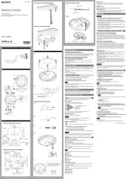
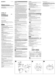
Location and Function of Part
The figure shows the camera without the dome casing.
Side
Audio cable (supplied and connected to the camera at the factory)
The connector with the longer cable (SP) is used for the line output connector,
and the shorter cable (MIC) is used for the microphone/line input connector.
SP terminal (minijack, monaural) ˎ
Connect a commercially available speaker system with a built-in amplifier.
MIC terminal (minijack, monaural) ˎ
Connect a commercially available microphone. This jack supports plugin-
power microphones (rated voltage: 2.5 V DC).
I/O (Input/Output) cable (supplied and connected to the camera at
the factory)
This cable is provided with two sensor inputs and two alarm outputs.
The wires of the cable control the following signals.
Color of wire Name
Red Sensor In 1+
White Sensor In 2+
Black Sensor In – (GND)
Yellow Alarm Out 1+
Brown Alarm Out 1–
Green Alarm Out 2+
Blue Alarm Out 2–
For details on each function and required settings, see the User’s Guide.
For the wiring, see “Connecting the I/O cable” overleaf.
Wiring slit
Feed the wire rope through this.
For details, see “Installing the Camera.”
Base (PAN)
Camera block
Lens
LAN cable (RJ-45) (supplied and connected to the camera at the
factory)
Connect this cable to a hub or computer on the 10BASE-T or 100BASE-TX
network using a commercially available network cable (UTP, category 5).
Power input cable (supplied and connected to the camera at the
factory)
Connect this cable to a 24 V AC or 12 V DC power supply system.
You can screw an extension cable in the connector tip attached at the end of the
cable. Connect GND to the FG terminal (center of 3-pin connector). See
illustration overleaf.
BNC cable (supplied and connected to the camera at the factory)
Outputs a composite video signal.
Side conduit hole (3/4 inches NPT or M27 (2.0 mm (3/32 inches)-pitched,
hole diameter ø27 mm (1 1/8 inches)))
Connect a pipe to this hole. There is a conduit hole on the side of the camera
unit. The conduit hole cover is installed in the side conduit hole at the factory.
Remove the cover as needed and connect the pipe to the hole.
An M25 cable gland can be connected to the hole by removing the nut inside
the camera unit.
Note
Take care not to trap the cables between the camera and the ceiling or the wall. If
the cable is trapped, it may cause a fire or electric shock due to breaking.
Camera head
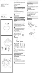
Inside
Camera unit
ZOOM/FOCUS switch
Use this switch to adjust lens’ zoom and focus. Slide the switch lever to select the
desired function.
[W] WIDE: Zoom out
[T] TELE: Zoom in
[N] NEAR: Focus on a nearby subject
[F] FAR: Focus on a distant subject
Hold down the center of the ZOOM/FOCUS switch for a moment to focus automatically.
Camera unit mounting screws (four positions)
Make sure to tighten the screws securely when installing the camera.
AC / DC IN (power input) connector
Connect the supplied power input cable to this connector.
MONITOR output jack
Connect this jack to a video input connector of a video monitor. You can adjust
the camera or lens while looking at the image on the video monitor. After
adjusting the camera or lens, disconnect the cable.
Camera block fixing screws (tilt) (two positions)
Firstly, loosen the screws and point the camera block in the desired direction,
then tighten the screws to secure in place.
Nut (3/ inches NPT or M27 (2.0 mm (43/ inches)-pitched))32
Safety cord
This cord prevents the dome casing from falling off the unit.
TOP mark
Indicates the image direction.
LAN network port (RJ-45)
Connect a commercially available network cable (UTP, category 5) to
communicate with a network or PoE/PoE+* system.
For details on connection, see the Instruction Manual of the power supply equipment.
(*PoE/PoE+ stands for Power over Ethernet. It is pursuant to IEEE802.3at.)
Dome casing
The dome cover is made of polycarbonate. A waterproof rubber gasket is
provided on the joint surface to the unit.
SD card slot
This slot is used for optional SD memory cards.
Image data in the camera can be recorded to a memory card by inserting it into
the slot.
Gently insert an SD card in (see illustration) until it clicks into place.
This unit is only compatible with SD and SDHC memory cards.
Note
For inquiries regarding verified SD memory cards, contact your authorized Sony
dealer.
POWER indicator (Green)
When the power is supplied to the camera, the camera starts checking the
system. If the system is normal, this indicator lights up.
HEATER indicator (Green)
The indicator lights up in green when the built-in heater is working normally.
NETWORK indicator (Green/Orange)
The indicator lights up or flashes when the camera is connected to the network.
The indicator is off when the camera is not connected to the network.
Reset switch
To reset the camera to the factory default settings, hold down this switch with a
point and supply the power to the camera.
Mode setting DIP switches
DIP switch function/settings
Switch No. 1 2
VIDEO POWER
Up (ON) PAL PoE+, AC, DC
Down (OFF) NTSC PoE
1 VIDEO (NTSC/PAL) switch (Initial setting: NTSC)
Switches the video output.
After setting the switch, reboot the camera unit.
2 POWER (PoE+, AC, DC/PoE) switch (Initial setting: PoE+, AC, DC)
Switch PoE+, AC, DC/PoE, depending on the power source you are using.
Note
When power is supplied by IEEE802.3at (PoE+) equipment, if the switch is set to
PoE, the range of activation and operating temperature is limited.
When power is supplied by IEEE802.3af (PoE) equipment, if the switch is set to
PoE+, the camera will not work properly.
When power is supplied from the AC or DC source and if the switch is set to PoE,
the heater will not work. Note that if you use the camera in a low temperature,
the camera may not work.
EXT CTRL (external control input/output) connector
Connect the supplied I/O cable to this connector.
AUDIO connector
Connect the supplied audio cable to this connector.
VIDEO OUT (video output) connector
Connect the supplied BNC cable to this connector.
Bottom
Cable holder (supplied and connected to the camera at the factory)
Packing for waterproofing the cables.
Holder plate
Fixes the cable holder.
GND
Ground the camera when you install it.
Note
Use the supplied Screws (M4 × 8)
Holder plate fixing screws (three positions)
Fixes the holder plate.
Rating label
Shows the name of this camera and its electric rating.
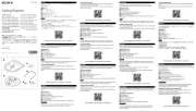
Preparations
Change connections and cable wiring
All the supplied cables are connected to the camera at the factory.
To change connections and cable wiring to suit your requirements, perform the
following steps.
When you route the cables from the side of the camera unit, see “Connecting to
the side conduit hole”.
a) If you use the camera with its factory setting
The preparation is completed.
b) If you use the LAN cable only
1 Loosen the four screws of the dome casing using the supplied wrench and
remove the dome casing.
2 Loosen the three holder plate fixing screws on the bottom to remove the
holder plate and cable holder.
3 Disconnect all the cables from the connectors and remove them from the
cable holder.
4 Insert the LAN cable through the hole of the LAN cable holder (replace the
cable holder with the LAN cable holder).
5 Insert the LAN cable through the bottom hole and adjust the length of the
LAN cable from the hole to the LAN port.
6 Connect the LAN cable to the LAN port.
7 Attach the removed holder plate to the bottom hole with the three holder
plate fixing screws.
c) For other cases
1 Loosen the four screws of the dome casing using the supplied wrench and
remove the dome casing.
2 Loosen the three holder plate fixing screws to remove the holder plate and
cable holder.
3 Remove all the cables from the cable holder and disconnect unnecessary
cables from the connectors.
Notes
For case b), if you use your own LAN cable, keep its diameter
ˎ ø5.0 mm (7/ 32
inches) - ø6.0 mm (1/ inches). Otherwise, waterproof the bottom hole. 4
For case c), if you need to waterproof the camera, see “Important precautions”
ˎ
overleaf.
Do not pull on any cables forcefully, as a connection may become loose.
ˎ
If the cables are removed from the guides, pass the cables through the guides
ˎ
and secure them again.
For case c), do not attach the cable plate and cable holder.
ˎ
d) Connecting to the side conduit hole
All the cables are connected to the camera through the bottom hole at the
factory. If you want to use the side conduit hole, perform the following steps:
1 Remove the conduit hole cover.
2 Loosen the three holder plate fixing screws on the bottom to remove the
holder plate and cable holder.
3 Disconnect all the cables from the connectors, and pull them out through the
bottom hole.
4 Insert the necessary cables through the pipe, then through the supplied
cable holder (for conduit), and finally through the side conduit hole. ( -c-2)
5 Connect the cables to the connectors.
6 Secure the cables through the guides. ( -c-1)
7 Screw the removed conduit hole cover into the bottom hole.
Notes
If the bottom hole is dirty, the conduit hole cover cannot be fixed firmly. In this
ˎ
case, moisture may leak into the casing and this may cause a malfunction.
Wipe off the dust with a soft cloth, and fix the conduit hole cover firmly.
Cover the joint part of the pipe/cover with silicon sealant, etc. to prevent
ˎ
moisture from getting inside the casing.
The holder plate and the cable holder are not necessary when you attach the
ˎ
conduit hole cover to the bottom hole.
Be careful not to drop the conduit hole cover and nut (
ˎ -7) when installing or
removing the camera.
For details on using the supplied cable holder (for conduit), see “Important
ˎ
precautions” overleaf.
Installation
WARNING
If you attach the camera in the height such as the wall or the ceiling, etc.,
ˎ
entrust the installation to an experienced contractor or installer.
If you install the camera at a height, ensure that the installation location and
ˎ
its material are strong enough to withstand a weight of 15 kg (33 lb 11 oz) or
more, and then install the camera securely. If the ceiling is not strong enough,
the camera may fall and cause serious injury.
To prevent the camera from falling, make sure to attach the supplied wire rope.
ˎ
If you attach the camera to the ceiling, check periodically, at least once a year,
ˎ
to ensure that the connection has not loosened. If conditions warrant, make
this periodic check more frequently.
Deciding the Installation Location of the Camera
After deciding the direction in which the camera will shoot, make the required
hole (ø73 mm (2 7/ inches)) for the connecting cables using the supplied 8
template. Then decide the four mounting hole positions to install the bracket.
Mounting screws
The supplied bracket is provided with eight ø4.5 mm ( 3/ inches) mounting 16
holes. Install the bracket on a ceiling or wall with screws through four mounting
holes: two 83.5 mm (3 9/ inches)-pitched holes or four 85.7 mm (3 32 3/ inches)-8
pitched holes. The required mounting screws differ depending on the installation
location and its material. (Mounting screws are not supplied.)
Steel wall or ceiling: Use M4 bolts and nuts.
Wooden wall or ceiling: Use M4 tapping screws. The panel thickness must be
15 mm (5/ inches) or more.8
Concrete wall: Use anchors, bolts and plugs suitable for concrete walls.
Junction box: Use screws to match the holes on the junction box.
WARNING
The required mounting screws differ depending on the installation location and
its material. If you do not secure the camera with the appropriate mounting
screws, the camera may fall off.
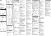
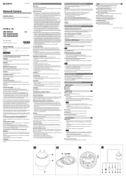
Installing the Camera
1 Remove the dome casing.
Loosen the screws with the wrench (supplied).
Pull up and remove the dome casing. When the screw catches on the
screw hole, pull up the screw.
2 Install the supplied bracket on the ceiling or wall.
Refer to “Mounting screws” for screws to be used.
3 Fix the supplied wire rope to the camera unit and the ceiling or wall.
Fix the wire rope with the supplied Screw M4 × 8 to the hole for the
wire rope on the bottom of the camera unit.
Fix the wire rope to the ceiling or wall.
When you install the camera on a wall, feed the cables through one of the
wiring slits. ( -3)
4 Attach the camera unit to the bracket with the supplied four camera unit
mounting screws.
The screws have a fall-prevention mechanism. The screws inserted into the
screw holes of the camera unit do not fall even if you turn the camera unit
upside down.
Insert the two holders to any two of the four grooves on the bracket.
Turn the camera clockwise until the locating pins snap to the holes on the
holders. Then the four camera installation holes will align the projections on
the bracket accordingly. There are four projections with an angle of
90 degrees, so you can select one of four directions.
Then tighten the four camera unit mounting screws to attach the camera unit
to the bracket through the camera installation holes.
Note
If you cannot use screws on a ceiling or wall, or if you want to make the camera
less conspicuous, use the YT-ICB45 in-ceiling bracket (optional) with which you
can mount the camera on the ceiling.
For this model, install the camera to the position on the side brackets of
YT-ICB45. Refer to the Installation Instructions of YT-ICB45 for detail information.
(continued overleaf)