Theben LUXA 104 S360-200-24 DE-UP WH Manual
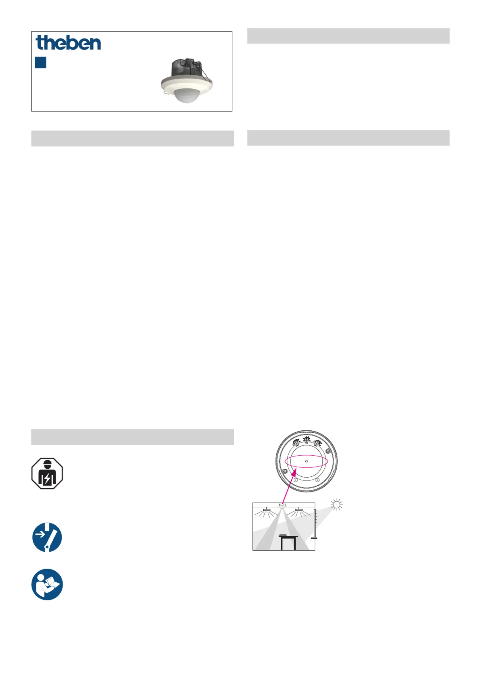
Theben Bevægelsesdetektor LUXA 104 S360-200-24 DE-UP WH

Læs gratis den danske manual til Theben LUXA 104 S360-200-24 DE-UP WH (9 sider) i kategorien Bevægelsesdetektor. Denne vejledning er vurderet som hjælpsom af 4 personer og har en gennemsnitlig bedømmelse på 4.3 stjerner ud af 2.5 anmeldelser. Har du et spørgsmål om Theben LUXA 104 S360-200-24 DE-UP WH, eller vil du spørge andre brugere om produktet?

Side 1/9
1
LUXA 104 S360-200-24 DE-UP WH
1040200
307485
06.02.2023
Presence detector
EN
1. General information
Passive infrared presence detector with 2 lighting chan-
nels for ceiling installation (false ceiling), ush mounting
in standard box and surface mounting
Circular detection area 360°, up to Ø 24 m (452 m
2
)
Restriction of detection area with cover clips
2 mixed light measurements
Settings via potentiometer or remote control
Fully or semi-automatic operation, switchable
Brightness setpoint value adjustable, teach-in function
Reduction of time delay when present briey (short-term
presence)
Pulse function for staircase light timer switch
Congurable time delay
Congurable detection sensitivity
Ready for immediate use due to factory presetting
Test mode for checking function and detection area
Extension of detection area via master/slave or master/
master switching
Optional accessories:
Surface-mount frame 100A WH (9070819)
theSenda S user remote control (9070911) (theSenda S
for short), theSenda P service remote control (9070910)
(theSenda P for short), theSenda B app remote control
(9070985) and the corresponding theSenda Plug app
(iOS/Android) (theSenda B/app for short)
2. Safety
Assembly and installation should only be carried
out by a qualied electrician, somebody who has
completed appropriate professional training and
has the knowledge and experience necessary to be
able to recognise and avoid the potential dangers
posed by electricity.
Before installation/disassembly, disconnect the
power supply and ensure that the parts are no
longer live.
Prior to commissioning and using the product, read
and observe all the operating instructions.
The presence detector conforms to EN 60669-2-1 if correctly
installed.
3. Proper use
Presence detector for presence and brightness-depen-
dent lighting control
Suitable for ceiling installation (false ceilings), ush
mounting in standard box or surface mounting in inte-
riors (ofces, meeting rooms, classrooms, warehouses,
sports halls, garages, etc.)
4. Installation
Installation instructions
As the detector reacts to variations in temperature, avoid the
following situations:
Do not point the presence detector at objects with highly
reective surfaces such as mirrors, etc.
Do not install the presence detector near heat sources such
as heating vents, air conditioners, lamps, etc.
Do not point the presence detector at objects that move in
the wind such as curtains, large plants, etc.
Pay attention to the direction of motion during the test run.
LPrior to installation, you may need to make settings at the
potentiometers.
LObserve the recommended installation height of 2 – 5 m.
LEnsure that there are no obstructions as infrared rays
cannot pass through solid objects.
LLight measurement L1 is assigned to lighting channel 1
and light measurement L2 is assigned to lighting channel
2. This must be taken into consideration when installing
the detector.
Example: If light measurement L1 is directed towards the
window, lighting channel 1 (terminal connection ↑1)
must also be provided at the window.
L2 L1
L1L2
1
2
Place the bezel frame on the housing so that the notches
line up.
Turn the cover ring clockwise briey until it clicks into place.
2
L2
L1
LIf the bezel frame is mounted as shown in the gure, the
alignment of the light measurement can also be identied
when it is installed. The arrow marking shows where light
measurement L2 is.
Disconnect the power source prior to installation.
Installation in false ceiling (ceiling installation)
Create a ceiling opening of approx. Ø 68 mm.
Strip the cable to 6 – 8 mm.
Assemble and connect the device as shown in the gure.
Ø = 68
6 - 8 mm
30 - 35 mm
Screws
Flush mounting
Remove the ceiling installation box from the detector.
Strip the cable to 6 – 8 mm.
Assemble and connect the device as shown in the gure.
6 - 8 mm
20 - 30 mm
t
Fixing plate
Secured
screws
Turn anticlockwise
and remove
Decorative
ring
Detector
Installation
frame
LA box with a minimum depth of 40 mm provides the opti-
mum installation conditions.
Surface mounting
Strip the cable to 6 – 8 mm.
Assemble and connect the device as shown in the gure.
LIP 54 protection.
6 - 8 mm
30 - 35 mm
e
r
Secured
screws
Turn anticlockwise
and remove
Decorative
ring
Detector
Surface-mount
frame 9070819
Detection area
A
S
T
Installation
height (A)
Walking persons
frontal (r)
Walking persons
across (t)
Seated persons
(s)
2.5 m 28 m
2
Ø 6 m 452 m
2
Ø 24 m 28 m
2
Ø 6 m
All gures are guidance values.
Limiting the detection area
Use the enclosed cover clip to adjust the detector to the
desired detection area.
Remove the required section of the clip using scissors.
Then place it on the lens.


Produkt Specifikationer

Mærke: Theben
Kategori: Bevægelsesdetektor
Model: LUXA 104 S360-200-24 DE-UP WH

Har du brug for hjælp?

Hvis du har brug for hjælp til Theben LUXA 104 S360-200-24 DE-UP WH stil et spørgsmål nedenfor, og andre brugere vil svare dig