Valcom V-9908 Manual


Læs gratis den danske manual til Valcom V-9908 (6 sider) i kategorien Intercomsystem. Denne vejledning er vurderet som hjælpsom af 20 personer og har en gennemsnitlig bedømmelse på 4.3 stjerner ud af 10.5 anmeldelser. Har du et spørgsmål om Valcom V-9908, eller vil du spørge andre brugere om produktet?

Side 1/6
9479801
Issue 1
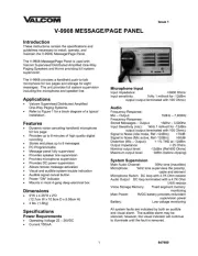
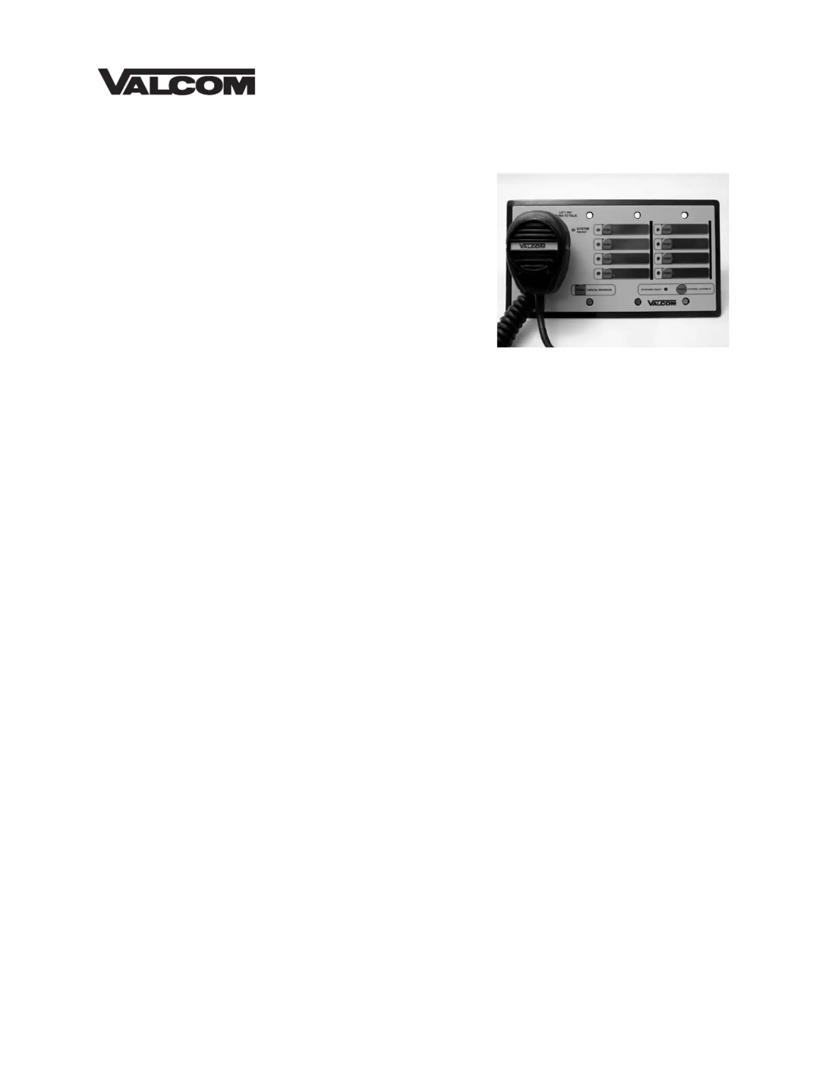
V-9908 MESSAGE/PAGE PANEL
Introduction
These instructions contain the specifications and
guidelines necessary to install, operate, and
maintain the V-9908, Message/Page Panel.
The V-9908 Message/Page Panel is used with
Valcom Supervised Distributed Amplified One-Way
Paging Speakers and Horns providing full system
supervision.
The V-9908 provides a handheld push-to-talk
microphone for live pages and storage for eight
messages. The unit provides full system supervision
including the microphone and speaker line.
Applications
Valcom Supervised Distributed Amplified
One-Way Paging Systems.
Refer to Figure 1 for a block diagram of a typical
installation.
Features
Dynamic noise canceling handheld microphone
for live page
Provides up to 8 minutes of high quality digital
recording
Stores and plays up to 8 messages
PC Programmable
Message panel fully supervised
Provides speaker line supervision
Provides microphone supervision
Provides DC power supervision
Allows remote message activation
Visual and audible system trouble indication
Audible signal cancel button
Power "ON" indicator
Mounts in most 4 gang deep electrical box
Dimensions
5"W x 4.25"H x 2”D
(12.7cm W x 10.8cm D x 5.08cm H)
4 lbs. (1.5Kg)
Specifications
Power Requirements
Operating Voltage 22 – 26VDC
Current 100mA
Microphone Input
Input Impedance: >5000 Ohms
Input sensitivity: 1kHz 1 millivolt for -12dBm
output (output terminated with 100 Ohms)
Audio
Frequency Response:
Mic – Output: 150Hz – 7,000Hz
Frequency Response:
Stored Messages – Output: 150Hz – 3,500Hz
Input Sensitivity (mic): 1kHz 1 millivolt for -12dBm
output (output terminated with 100 Ohms)
Signal to Noise (Idle mode, Ref -12dBm): >70dB
Signal to Noise (Mic active, Ref -12dBm) >50dB
Distortion (Mic – Output): < 1% THD at -12dBm
Output Impedance: < 25 Ohms
Nominal output level: -12dBm (Ref 600 Ohms)
Maximum output level: 0dBm (before clipping)
System Supervision
Main Audio Channel: 30Hz tone (inaudible)
Microphone: 1kHz tone supervises the preamp,
cable and element
Microphone Switch: DC loop with 4.7K Ohm resistor
Audio Output: DC loop terminated with a 4.7K Ohm
1/4W resistor
Voice Storage Memory: Fixed segment memory
monitoring
Main Power: 9VDC battery provides redundant
supervision power
Battery: Low voltage monitoring
All system faults are indicated by both an audible
and visual alarm. The audible alarm may be
silenced, however, the visual indicator will continue
to illuminate until the fault is removed.
9479802
User Controls (Figure 1)
Push-to-Talk Microphone
Pushbuttons to activate pre-recorded messages
Pushbutton to cancel message play
Pushbutton to cancel wire fault alarm
Indicators (Figure 1)
Power “ON”
Individual message play
Visual system fault
Audible system fault with silence button
Inputs (Figure 2)
Eight remote message activation inputs via
single pole pushbutton switches.
RS-232 provided for message uploads and
downloads.
Handheld microphone for “live” announcements
Outputs (Figure 2)
Audio output
Page/Message active contact
Proprietary RS-485 for system status reporting
External security output (contact closure)
System Operation
The Push-to-Talk microphone is used for live pages.
The microphone has priority over message playback
paging. Pressing the Push-to-Talk switch on the
microphone will activate the audio output and
override (and CANCEL) any message playback in
process.
A group of eight (8) front panel buttons with
associated LED’s are used to activate stored
messages. When a message is activated, the LED
will indicate the status. If the message is playing,
the LED will illuminate. Messages are not
chainable. A message must be finished before an
additional message may be activated. If a message
button is pressed while a message is playing the
original message will cancel.
A “MESSAGE CANCEL” button is available to
cancel any message playing.
Using the program tool, all messages can be
programmed for the following play scenarios:
1 play per button activation
2 plays per button activation
3 plays per button activation
Continuous plays per activation (cancelled via
“MESSAGE CANCEL” button)
Programming Voice Messages
A serial port (RS-232) is provided to upload and
download voice messages. The program tool
provides all editing and message processing (AGC,
response shaping, wave file conversions, etc.).
The final format is standard 8 bit uLaw at 8kHz
compressed format.
Although it is possible to upload and download
during system operation, it is recommended to
perform this function when the system is not in use.
This insures that messages will not be corrupted
during a download of upload. After message write
remove battery and DC power momentarily.
Total voice message storage is 8 minutes and there
are no other restrictions on lengths of individual
messages. It is possible to record tones, signals,
etc. that will operate in the voice band range. For
additional programming information refer to the
Message Control Panel Program Tool Help Menu.
System Fault Monitoring
The main audio channel has an inaudible tone
present whenever a page or message is not active.
This tone will verify the integrity of the audio channel
from the microphone to the audio output. In addition
the audio and power pairs of the speaker line are
monitored for shorts, opens and grounds. A V-9999
End of Line device is used to terminate the speaker
line.
Note: For Full System Supervision, Use Only
Valcom One-Way Supervised Speakers And
Horns With The Page Panel.
Proper operation of the voice memory flash device is
monitored by continuous reading a fixed segment of
the memory. This insures the flash memory integrity
as well as the circuitry that attaches it to the DSP
controller. It will detect defective components and
interconnection faults as well as actual memory
failure.
In the event of a system, wire or power failure, the
“System Fault LED will illuminate and an audible
alarm will sound. The audible alarm may be
silenced by pressing the “Cancel Audible” button,
however the “System Fault” light will continue to
illuminate until the fault has been corrected. A 9 Volt
battery located on the back of the Page Panel
provided the necessary power to operate the fault
circuits in the event of a power failure. The 9 Volt
battery is monitored and a system fault will occur
when the battery voltage drops. A contact closure is
available to signal a remote monitoring panel when a
system fault occurs.
Installation
Figure 1, shows microphone, message activate and
fault indication control locations. Figure 2 shows
remote message activate terminal connections
output connections, programming and power
connections located on the back of the message
panel. Figure 3 shows a typical connecting
arrangement and other feature connections.
Referring to Figure 3, connect 24VDC as indicated.


Produkt Specifikationer

Mærke: Valcom
Kategori: Intercomsystem
Model: V-9908

Har du brug for hjælp?

Hvis du har brug for hjælp til Valcom V-9908 stil et spørgsmål nedenfor, og andre brugere vil svare dig


Intercomsystem Valcom Manualer

Valcom

Valcom V-1072B Manual

6 September 2024
Valcom

Valcom V-1074 Manual

6 September 2024
Valcom

Valcom V-2972 Manual

6 September 2024
Valcom

Valcom V-9953 Manual

6 September 2024
Valcom

Valcom V-TR96 Manual

6 September 2024
Valcom

Valcom V-5324004 Manual

6 September 2024
Valcom

Valcom V-9908 Manual

6 September 2024
Valcom

Valcom V-9923B Manual

6 September 2024
Valcom

Valcom V-1096 Manual

6 September 2024

Intercomsystem Manualer

Nyeste Intercomsystem Manualer