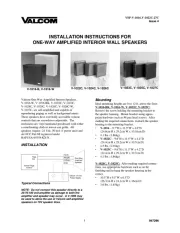
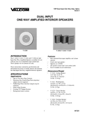
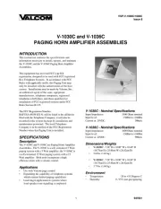
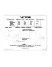
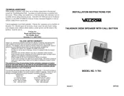
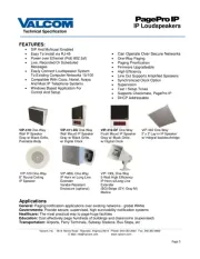
Valcom V-9945A Manual

Valcom Højttaler V-9945A

Læs gratis den danske manual til Valcom V-9945A (4 sider) i kategorien Højttaler. Denne vejledning er vurderet som hjælpsom af 23 personer og har en gennemsnitlig bedømmelse på 4.5 stjerner ud af 12 anmeldelser. Har du et spørgsmål om Valcom V-9945A, eller vil du spørge andre brugere om produktet?

Side 1/4
VSP- -V 9945A
Issue 7
1 947747
V-9945A
SINGLE TONE/INTERRUPTED
WARBLE TONE LOUD HORN
INTRODUCTION
The V- -9945A is a horn with built in tone generator
and amplifier used for loud signaling applications.
These instructions provide identification, connection,
installation, operation and maintenance information
for the V-9945A, Single Tone/Interrupted Warble
Tone Horn Ringer.
SPECIFICATIONS
Purpose
The V-9945A provides amplified electronic tones for
signaling in large or noisy areas or outside.
Applications
Night ringing
C. O. audible ringing
Time clocks
Special purpose signaling
Features
Self-contained tone generator, amplifier, volume
control and horn speaker
Single tone or warble tone outputs
Power supply included
Activated by dry contact closure
Single tone will override warble tone
Warble tone interrupted 1 second on, 5 seconds
off
Single tone continuous for duration of closure
Weatherproof
Units may be multipled for simultaneous access
Capacity
The V-9945A has provisions for two inputs, either or
both of which can be used in an application. If both
inputs are activated simultaneously, the single tone
will override the warble tone.
The V-9945A is a stand alone ringer horn activated by
a relay. If more than one ringer horn is required,
contact Valcom Technical Support at (540) 563-2000
for design assistance.
Dimensions/Weight
6.50"H x 8.20"W x 10.40"D, plus mounting
bracket
(16.51cm H x 20.83cm W x 26.42cm D)
4.3 lbs. (1.95 kg)
Power Requirements
-21.5 to -26.0VDC "B" battery, 250mA nominal.
Environment
Temperature: -20 to +55 degrees C
Humidity: 0 to 95% non-precipitating
DESIGN
Access Requirements
The V-9945A requires a dry contact closure for
activation of each tone (If both tones will be used,
two closures are required). The closures may be in
the form of night ringing relay contacts, time clock
contacts, a standard normally open switch or
equivalent.
2
Equipment Requirements
A system using the V-9945A will consist of the
following:
Access equipment (See Design Section)
-24VDC power supply (Included with horn)
INSTALLATION
General
These instructions cover only the installation
procedure for the Valcom V-9945A. Please consult
practices for other equipment if any other equipment
is being used.
TELEPHONE SYSTEM
NIGHT RING
CONTACT
CLOSURE
RED
GREEN
BROWN
WHITE
BLACK
V-9945A
-24VDC
POWER SUPPLY
TIME CLOCK
CONTACT
CLOSURE
FIGURE 1 - TYPICAL INSTALLATION
Precautions
All precautions have been taken at the factory to
insure that the equipment functions properly. To
insure proper operation and to prevent equipment
damage, please observe the following:
Unplug the power supply before making any
connections to the unit.
Do not apply power to the unit until all
connections have been double-checked.
Attaching Speaker to Base
NOTE: For ease of installation, the base can be
attached to the speaker before or after the base is
mounted.
Loosen position adjustment knob.
Insert the ball of the base into the socket of
the speaker.
Tighten the position adjustment knob.
Mounting
The V-9945A should be mounted 12 feet to 25 feet
high in the area requiring signaling. The unit can be
mounted to a wall, a beam or an electrical box.
Mount the base to a wall using the two holes
provided. Knockout holes are provided for
punch out should additional holes be
desired.
A "C" clamp is provided with the ringer to
allow mounting to a beam. Place the bolt
through the hole in the bottom of the base to
secure the "C" clamp to the beam. (See
Figure 2).
Connection to an electrical backbox is
accomplished by channeling wire through
the ball of the base (See Figure 3) and
making appropriate connections. The base
has holes punched for a double-gang square
box, but by punching out additional
knockout holes, the base can be mounted to
a single-gang or octagon box.
The V-9945A may be rotated or moved up and down
to obtain the desired position by loosening the knob
(See Figures 2 and 3) at the bottom of the unit
approximately 1 turn. Make required adjustment and
re-tighten knob.
Lead Designations
Black Ground (+)
White -24VDC
Red Warble tone access
Green Common
Brown Single tone access
Connections
Connections should be accomplished using twisted
pair telephone wire. The power supply should be
located within 500 feet of the horn.
Connect negative (-)(-24VDC) lead of the
power supply to the white lead; connect
positive (+)(Gnd) lead of the power supply to
the black lead.
For warble tone access, connect contact
closure between red and green.
For single tone access, connect contact
closure between brown and green.
Connections for both single tone and warble tones
may be made to the same speaker.


Produkt Specifikationer

Mærke: Valcom
Kategori: Højttaler
Model: V-9945A

Har du brug for hjælp?

Hvis du har brug for hjælp til Valcom V-9945A stil et spørgsmål nedenfor, og andre brugere vil svare dig


Højttaler Valcom Manualer

Valcom

Valcom VIP-421 Manual

6 September 2024
Valcom

Valcom VIP-422A Manual

6 September 2024
Valcom

Valcom V-1019B Manual

6 September 2024
Valcom

Valcom V-1020C Manual

6 September 2024
Valcom

Valcom S-522A-2 Manual

6 September 2024
Valcom

Valcom Clarity S-515 Manual

6 September 2024
Valcom

Valcom V-1023C Manual

6 September 2024
Valcom

Valcom V-1040 Manual

6 September 2024

Højttaler Manualer

Nyeste Højttaler Manualer

Musicozy

Musicozy GH01 Manual

14 Juni 2025
ZAPUVO

ZAPUVO H77 Manual

14 Juni 2025
DinDin

DinDin BB-S3 Manual

14 Juni 2025
MUZEN

MUZEN MW-P1I Manual

14 Juni 2025
Turtlebox

Turtlebox Gen 2 Manual

14 Juni 2025
KMAG

KMAG HB1 Manual

14 Juni 2025
Fiodio

Fiodio F-510 Manual

14 Juni 2025