Vimar 01450 Manual


Læs gratis den danske manual til Vimar 01450 (6 sider) i kategorien Energiomkostningsmåler. Denne vejledning er vurderet som hjælpsom af 15 personer og har en gennemsnitlig bedømmelse på 4.8 stjerner ud af 8 anmeldelser. Har du et spørgsmål om Vimar 01450, eller vil du spørge andre brugere om produktet?

Side 1/6
Viale Vicenza, 14
36063 Marostica VI - Italy
www.vimar.com
49400547A0 06 2202
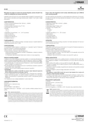
01450
SMART AUTOMATION BY-ME PLUS
ESEMPI DI COLLEGAMENTO
Misuratore di energia, 3 ingressi per sensore di corrente toroidale, potenze rilevabili 25 W-100 kW, alimentazione monofase 120-230 V 50/60 Hz trifase 230/400 V
50/60 Hz, installazione su guida DIN (60715 TH35), occupa 1 modulo da 17,5 mm. Fornito con un sensore di corrente toroidale (art. 01457).
Il dispositivo misura la potenza in una o più linee di rete.Pfunzionare sia su impianti
monofase che trifase e può monitorare in modo indipendente fino a 3 linee elettriche.
La misura della corrente sulla linea elettrica da controllare viene eseguita per mezzo di
una sonda di corrente (art. 01457, 01458). Effettua infine l’archiviazione storica dei valori
dell’energia di ognuna delle linee.
CARATTERISTICHE.
Tensione nominale di alimentazione:
- L1-N: 120-230 V 50/60 Hz.
- L1-L2-L3-N: 127/200 V 50/60 Hz; 230/400 V 50/60 Hz.
Tensione nominale di alimentazione bus TP: 29 V
Assorbimento: 5 mA
Potenze rilevabili: da 25 W a 100 kW (fino a 33 kW per ogni linea)
Morsetti: bus TP, tensione alimentazione (trifase + N), ingressi per sensori di corrente
(art. 01457, 01458)
Temperatura di funzionamento: + 5 °C - +40 °C (da interno)
1 modulo da 17,5 mm
Grado di protezione: IP20
Categoria di sovratensione: III
Categoria di misura: III
FUNZIONAMENTO.
Misure:
- Rilevazione della potenza attiva su un max di 3 linee (L1, L2 e L3)
N.B. Se viene visualizzato un valore negativo della potenza a carico, invertire il
relativo sensore di corrente.
- Contatore di energia parziale e assoluto
- Archiviazione storica dell’energia della linea su base oraria, giornaliera, mensile e annuale
Parametri: per la descrizione dettagliata di tutti i parametri si veda il manuale del
sistema By-me Plus
LED: Led di configurazione
CONFIGURAZIONE.
PER LE OPERAZIONI DI CONFIGURAZIONE, SI VEDA IL MANUALE DEL SISTEMA
By-me Plus.
Blocchi funzionali: 3 (uno per ogni linea); ogni blocco può appartenere al massimo
a un gruppo.
Selezione dei blocchi funzionali:
- Durante la creazione dei gruppi, quando viene richiesto, premere brevemente il pul-
sante di configurazione del dispositivo per un numero di volte pari al blocco funzionale
che si vuole selezionare (ad esempio premere 2 volte per selezionare il blocco 2); la
frequenza di lampeggio del LED di configurazione aumenta progressivamente con
l’aumentare del numero del blocco funzionale.
La mancanza di pressione per un tempo di 3 s implica la fine della selezione.
- Quando il led di configurazione è acceso viene configurato il blocco funzionale; al
termine dell’operazione il led si spegne.
REGOLE DI INSTALLAZIONE.
L’installazione deve essere effettuata da personale qualificato con l’osservanza delle
disposizioni regolanti l’installazione del materiale elettrico in vigore nel paese dove i
prodotti sono installati.
Prima di operare sul dispositivo assicurarsi di togliere tensione agendo sull’in-
terruttore generale di ogni linea collegata (L1, L2 e L3).
• Il dispositivo deve essere protetto con un interruttore automatico facilmente accessibile.
Attenzione: I due morsetti di neutro sono collegati tra di loro. Non utilizzare i
morsetti di Neutro come uscite per alimentare il carico
In caso di impianto monofase connettere la tensione di rete ai morsetti L1 - N.
In caso di collegamento di psensori S2 e/o S3 è necessario collegare le rispettive
fasi L2 e/o L3.
Il presente dispositivo è conforme alla norma di riferimento, in termini di sicurezza
elettrica, quando è installato nel relativo centralino.
Se il dispositivo viene utilizzato per scopi non specificati dal costruttore, la protezione
fornita potrebbe essere compromessa.
• Rispettare i valori di corrente e tensione massimi indicati per il dispositivo.
CONFORMITANORMATIVA.
Direttiva BT. Norme EN 61010-1, EN 61010-2-030.
Direttiva EMC. Norme EN 61000-6-1, EN 61000-6-3.
Regolamento REACh (UE) n. 1907/2006 – art.33. Il prodotto potrebbe contenere tracce
di piombo.
VISTA FRONTALE/LATERALE E MORSETTI
SENSORE DI CORRENTE art. 01457-01458
Pulsante di
configurazione
Ingressi per
sensore
di corrente
Morsetti per collegamento linea
Morsetti bus TP
Cavo per ingresso ai
morsetti S del
misuratore di energia
Sensore di
corrente toroidale
La lunghezza del cavo di collegamento del sensore
di corrente è di 400 mm per cui, per effettuare la
misura locale, predisporre in modo opportuno il
cablaggio dei cavi di linea all’interno del quadro
elettrico.
Il sensore di corrente deve essere installato in modo
che il lato in cui è presente l’etichetta sia rivolto
verso il contatore di energia della linea (produzione).
PA3832 N L
DATE CODE
CTRY OF MFG
PAT. PEND
L
N
Lato con etichetta
L1
Bus
L2
L3
N
IMPIANTO TRIFASE
Bus
L
N
S1
PRODUZIONE MONOFASE
Contatore
di produzione
RAEE - Informazione agli utilizzatori
Il simbolo del cassonetto barrato riportato sull’apparecchiatura o sulla sua confezione indica che il prodotto alla fine della propria vita utile deve essere raccolto separatamente dagli altri rifiuti. L’utente dovrà, pertanto, conferire l’apparecchiatura
giunta a fine vita agli idonei centri comunali di raccolta differenziata dei rifiuti elettrotecnici ed elettronici. In alternativa alla gestione autonoma, è possibile consegnare gratuitamente l’apparecchiatura che si desidera smaltire al distributore, al
momento dell’acquisto di una nuova apparecchiatura di tipo equivalente. Presso i distributori di prodotti elettronici con superficie di vendita di almeno 400 m 2 è inoltre possibile consegnare gratuitamente, senza obbligo di acquisto, i prodotti
elettronici da smaltire con dimensioni inferiori a 25 cm. L’adeguata raccolta differenziata per l’avvio successivo dell’apparecchiatura dismessa al riciclaggio, al trattamento e allo smaltimento ambientalmente compatibile contribuisce ad evitare
possibili effetti negativi sull’ambiente e sulla salute e favorisce il reimpiego e/o riciclo dei materiali di cui è composta l’apparecchiatura.
Viale Vicenza, 14
36063 Marostica VI - Italy
www.vimar.com
49400547A0 06 2202
01450
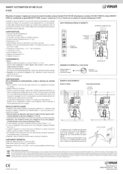
SMART AUTOMATION BY-ME PLUS
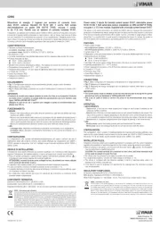
CONNECTION EXAMPLES
Power meter, 3 inputs for toroidal current sensor, detectable power 25 W-100 kW, single-phase power supply 120-230 V 50/60 Hz three-phase 230/400 V 50/60
Hz, installation on DIN rail (60715 TH35), occupies 1 17.5 mm module. Supplied with a toroidal current sensor (art. 01457).
FRONT/SIDE VIEW AND TERMINALS
CURRENT SENSOR art. 01457-01458
Configuration
button
Inputs for current
sensor
Terminals for three-phase line connection
TP BUS terminals
Input cable at terminals S
of the power meter Toroidal current sensor
The connecting cable of the current probes is 400
mm long so, in order to make the local measure-
ment, appropriately prepare the wiring of the line
cables inside the electric box.
The current probe must be installed so that the
side with the label is facing the line power meter
(generation).
Side with label
PA3832 N L
DATE CODE
CTRY OF MFG
PAT. PEND
L
N
L1
Bus
L2
L3
N
THREE-PHASE SYSTEM
Bus
L
N
S1
SINGLE-PHASE SYSTEM WITH GENERATION
Generation
meter
This device measures the power in one or more lines of a network.
It can work on both single and three phase systems and can independently monitor up
to 3 electrical lines. The current on the electrical line to be monitored is measured by a
current probe (art. 01457, 01458).
Lastly, it saves the history of the energy values of each of the lines.
CHARACTERISTICS.
Rated supply voltage:
- L1-N: 120-230 V 50/60 Hz.
- L1-L2-L3-N: 127/200 V 50/60 Hz; 230/400 V 50/60 Hz.
Rated supply voltage TP Busbar: 29 V
Absorption: 5 mA
Measurable power: from 25 W to 100 kW (up to 33 kW per line)
Terminals: TP busbar, power supply voltage (three-phase + N), inputs for current
sensors (art. 01457, 01458)
Operating temperature: + 5°C to +40°C (indoor)
1 module of 17.5 mm
Protection class: IP20
Overvoltage category: III
Measurement category: III
OPERATION.
Measurements:
- Measurement of active and reactive power on at most 3 lines (L1, L2 and L3)
N.B. If a negative power charge is shown, invert the relative current sensor.
- Partial and absolute power meter
- Power history of the line on an hourly, daily, monthly and yearly basis
Parameters: for all the details on the parameters, see the installer manual of the
By-me Plus system.
LED: Configuration LED
CONFIGURATION.
FOR THE OPERATIONS OF CONFIGURATION, SEE THE INSTRUCTIONS
MANUAL FOR THE By-me Plus SYSTEM.
Functional blocks: 3 (one for each line); each unit can belong to at most one group.
Selecting functional units:
- When creating groups, when required by the app, briefly press the device configura-
tion button a number of times equal to the functional block you want to select (for
example, press 2 times to select block 2). The LED blink frequency increases pro-
gressively as the number of the functional block increases.
Not pressing it for a time of 3 s implies the end of selection.
- When the red LED is on, the app is configuring the functional block; at the end of this
operation the LED will go out.
INSTALLATION RULES.
Installation should be carried out by qualified staff in compliance with the current
regulations regarding the installation of electrical equipment in the country where the
products are installed.
Before working on the device, switch the power off at the main switch for each line
connected (L1, L2 and L3).
• The device must be protected by an easily accessible circuit breaker.
Important: The two neutral terminals are connected to each other. Do not use the
neutral terminals as outputs to power the load.
On single-phase systems, connect the mains voltage to terminals L1 - N.
When connecting several S2 and/or S3 sensors, connect the respective phases L2
and/or L3.
This device is compliant with the reference standard, in terms of electrical safety,
when it is installed in the relevant consumer unit.
If the device is used for purposes not specified by the manufacturer, the protection
provided may be jeopardized.
REGULATORY COMPLIANCE.
LV directive. Standards EN 61010-1, EN 61010-2-030.
EMC directive. Standards EN 61000-6-1, EN 61000-6-3.
REACH (EU) Regulation no. 1907/2006 Art.33. The product may contain traces of
lead.
WEEE - Information for users
If the crossed-out bin symbol appears on the equipment or packaging, this means the product must not be included with other general waste at the end of its working life. The user must take the worn product to a sorted waste center, or
return it to the retailer when purchasing a new one. Products for disposal can be consigned free of charge (without any new purchase obligation) to retailers with a sales area of at least 400 m 2, if they measure less than 25 cm. An efficient
sorted waste collection for the environmentally friendly disposal of the used device, or its subsequent recycling, helps avoid the potential negative effects on the environment and people’s health, and encourages the re-use and/or recycling
of the construction materials.


Produkt Specifikationer

Mærke: Vimar
Kategori: Energiomkostningsmåler
Model: 01450

Har du brug for hjælp?

Hvis du har brug for hjælp til Vimar 01450 stil et spørgsmål nedenfor, og andre brugere vil svare dig


Energiomkostningsmåler Vimar Manualer
Vimar

Vimar 02960 Manual

15 December 2024
Vimar

Vimar 01451 Manual

15 December 2024
Vimar

Vimar 01450 Manual

15 December 2024

Energiomkostningsmåler Manualer

Nyeste Energiomkostningsmåler Manualer
Elektrobock

Elektrobock EMF-2 Manual

9 Januar 2025
Elro

Elro EC12 Manual

10 Oktober 2024
ORNO

ORNO OR-WE-522 Manual

5 September 2024
Schneider

Schneider METSEPM8244 Manual

5 September 2024
Schwaiger

Schwaiger SOEM0100 Manual

3 September 2024
Schwaiger

Schwaiger STEM1180 Manual

3 September 2024
PeakTech

PeakTech 9035 Manual

2 September 2024
MDT

MDT EZ-0320.01 Manual

31 August 2024