Viale Vicenza, 14
36063 Marostica VI - Italy
www.vimar.com
xx195 01 2203
LINEA
30195.x
EIKON
20195
ARKÉ
19195
PLANA
14195
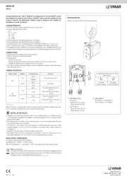
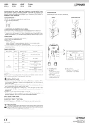
Access point Wi-Fi 802.11 b/g/n con 2 porte LAN 10-100Mb/s, ingresso per
pulsante remoto di accensione e spegnimento radio Wi-Fi, alimentazione 220-
240 V~ 50/60Hz- 2 moduli.
Il dispositivo è in grado di generare una rete wifi a 2.4GHz e, grazie alle due connessioni LAN
posteriori, la rete creata può essere collegata ad una rete LAN esistente o può rendere disponibili
due porte cablate a cui collegare dispositivi non wireless. E’ possibile disabilitare la sola parte
radio wifi agendo sul pulsante frontale o cablando un pulsante alla coppia di morsetti a molla
posteriori nel caso in cui il dispositivo sia installato in posizione non facilmente accessibile.
CARATTERISTICHE.
• Tensione di alimentazione: 220-240 V~, 50/60 Hz
• Potenza assorbita: 2,5 W
• Range di frequenza: 2412-2472 MHz
• Potenza RF trasmessa: < 100 mW (20 dBm)
• Velocità di trasmissione:
- connessione LAN (ethernet): 10-100 Mb/s
- connessione WiFi: 72,2 Mb/s max con canale a 20 MHz e 150 Mb/s con canale a 40 MHz
(larghezza canali impostabile via web browser; valore di default 20 MHz)
• Standard Wireless: 802.11 b/g/n
• Tipologie di Sicurezza/Cifratura disponibili:
- WPA-PSK, WPA2-PSK, mixed mode
- WEP open system/shared key
• Pulsante di accensione/spegnimento segnale WiFi e reset del dispositivo
• LED di stato segnale WiFi
• Possibilità di collegamento con pulsante remoto per accensione/spegnimento WiFi e reset del
dispositivo. Il pulsante da utilizzare deve essere un CONTATTO PULITO non alimentato.
• Grado di protezione: IP40
• Temperatura di funzionamento: -10..+40 °C (uso interno)
COLLEGAMENTI.
• Morsetti:
- a carrello per alimentazione 220-240 V~
- a molla per il collegamento del pulsante remoto (contatto pulito, ES1)
- a inserimento, estraibile per collegamento rete LAN (2 canali ethernet 100 base-TX, ES1) con
massimo isolamento del conduttore Ø 2,1 mm, 20-26 AWG.
• Sezione dei cavi:
- per alimentazione: 0,5-0,75 mm
2
- per collegamento plusante remoto: 0,5 mm
2
• Lunghezza max. del collegamento con il pulsante remoto: 20 m
• Cavi ethernet:
- Si consiglia di utilizzare cavi UTP di categoria CAT.5e o CAT.6.
- L'Access point è provvisto di due porte ethernet indipendendenti per ognuna delle quali vengo
-
no esportate le due coppie di conduttori necessarie al funzionamento in modalità 100base-TX
(colori: verde+bianco/verde e arancione+bianco/arancione).
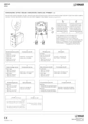
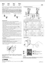
- Nell'impianto le coppie di conduttori vanno cablate secondo lo schema T568B (si veda la fig.
ESEMPIO DI COLLEGAMENTO).
• Lunghezza max. cavi ethernet: 100 m per ogni uscita RJ45.
FUNZIONAMENTO.
Il dispositivo consente di realizzare le seguenti tipologie di funzionamento:
1. Access point WiFi. Questa configurazione permette di realizzare una rete WiFi a partire da
una connessione alla rete cablata.
2. Estensione rete WiFi. Questa configurazione permette di estendere la copertura della rete WiFi
utilizzando l'access point come “ripetitore” del segnale; in questo caso è necessario impostare
nel dispositivo l’SSID e la password del router di casa.
Nota: Le stesse impostazioni dovranno essere modificate in accordo con eventuali variazioni
sul Router stesso effettuandole prima sull'Access point per non perdere il collegamento radio
WiFi.
3. Estensione rete LAN. Questa configurazione permette di estendere la rete cablata in una
zona che non è raggiungibile direttamente dal cavo. Per realizzare questa configurazione è
necessario impostare il dispositivo 1 in modalità “Access point WiFi” impostando una SSID ed
una password diverse rispetto a quelle del router principale, mentre il dispositivo 2 va imposta
-
to in modalità “Estensione rete LAN” immettendo la stessa SSID e password del dispositivo
1. Se si vuole mantenere la massima banda disponibile è possibile filtrare i dispositivi che si
possono connettere al dispositivo 1 abilitando il filtro Mac address dei dispositivi ammessi. E'
possibile selezionare la ripetizione del segnale WiFi.
Le porte ETH1 ed ETH2 per il collegamento delle reti LAN funzionano come uno switch.
Attenzione: In generale le funzionalità che prevedono la ripetizione del segnale WiFi (su WiFi
o su rete LAN come ad esempio nel funzionamento 2) non sono garantite per sorgenti diverse
dall'access point Vimar poiché la modalità di funzionamento necessaria non è uno standard e
potrebbe avere caratteristiche diverse a seconda del produttore.
Segnalazioni del LED frontale
• LED acceso: radio WiFi attiva
• LED spento: radio WiFi disattiva
• LED lampeggiante: reset in corso
• LED con sequenza due lampeggi rapidi - pausa: fase di programmazione della radio WiFi oppu
-
re assenza di collegamento verso l'Access point (tipologie di funzionamento 2 e 3)
• All'accensione del dispositivo il LED emette un breve lampeggio (l'avvio completo del disposi
-
tivo richiede circa 30 s).
Pulsante frontale e pulsante remoto
• Pressione breve: accensione o spegnimento WiFi (qualsiasi sia la tipologia di funzionamento).
• Pressione prolungata (almeno 10 s) entro 3 minuti dall'accensione del dispositivo: reset della
configurazione del dispositivo.
In caso di riavvio (spegnimento e riaccensione causato da una temporanea mancanza di
alimentazione) viene ripristinato l'ultimo stato del WiFi impostato; se era stato selezionato
spento il dispositivo si riavvia con WiFi spento mentre se era impostato acceso si riavvia con
WiFi acceso. L'operazione di reset comporta il ripristino della configurazione ai valori di default
previsti da Vimar.
Configurazione di default
• Modalità di default: Access Point
• Parametri IP: (IP statico192.168.1.225, NM: 255.255.255.0 )
• Tipologia di sicurezza: WPA2 PSK
• SSID default: VIMAR_AP
• Password per accesso WiFi: password
• Utente per accesso web: admin
• Password per accesso web: admin
La configurazione di default può essere personalizzata accedendo via web all’indirizzo IP di
default ed inserendo le proprie credenziali.
Prima configurazione
Per modificare la configurazione di default inserendo le impostazioni di funzionamento o di
indirizzo di rete desiderate e dialogare via LAN o WiFi con l’Access Point, è necessario che
il PC sia associato alla stessa sottorete del dispositivo con un indirizzo del tipo 192.168.1.x.
Per tutti i dettagli si veda il manuale scaricabile dal sito www.vimar.com in corrispondenza del
rispettivo codice articolo.
REGOLE DI INSTALLAZIONE.
• L’installazione e la configurazione devono essere effettuate da personale qualificato con l’osser-
vanza delle disposizioni regolanti l’installazione del materiale elettrico in vigore nel paese dove
i prodotti sono installati.
• Prima di effettuare l'installazione togliere la tensione di rete.
• Installare il dispositivo ad una altezza inferiore a 2 m.
• A fini della protezione contro i contatti diretti ed indiretti, in conformità all’articolo 528.1.1 della Norma
CEI 64-8, i cavi di rete LAN e pulsante remoto conformi alla norma CEI UNEL 36762 possono esse
-
re installati assieme, senza interposizione di setti separatori, ai cavi di energia utilizzati per sistemi a
tensione nominale verso terra (Uo) fino a 400 V.
• A monte dell’alimentatore deve essere installato un interruttore di tipo bipolare facilmente
accessibile con separazione tra i contatti di almeno 3 mm.
• Gli alimentatori costituiscono una sorgente SELV rispettando i requisiti previsti dall’articolo
411.1.2.2 della norma CEI 64-8 (ed. 2012).
• Per evitare interferenze di rete separare la tensione di alimentazione di componenti attivi e
dispositivi terminali (PC, ecc.) dalle altre utenze (ad esempio radio, TV, ecc.).
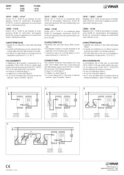
• In fase di manutenzione, per estrarre il conduttore del pulsante remoto dal morsetto, premere
con un utensile senza uscire dall'apposita sede e senza esercitare una forte pressione (si veda
INSTALLAZIONE fig. 7).
CONFORMITA' NORMATIVA.
Direttiva RED. Direttiva RoHS. Norme EN IEC 62368-1, EN 62911, EN 55032, EN55035, EN IEC
61000-3-2, EN 61000-3-3, EN 300 328, EN 301 489-17 (2017), EN IEC 62311 , EN IEC 63000.
Vimar SpA dichiara che l’apparecchiatura radio è conforme alla direttiva 2014/53/UE. Il testo
completo della dichiarazione di conformità UE è disponibile nella scheda di prodotto al seguente
indirizzo Internet: www.vimar.com.
Regolamento REACh (UE) n. 1907/2006 – art.33. Il prodotto potrebbe contenere tracce di piombo.
RAEE - Informazione agli utilizzatori
Il simbolo del cassonetto barrato riportato sull’apparecchiatura o sulla sua confezione indica che il prodotto alla fine della propria vita utile
deve essere raccolto separatamente dagli altri rifiuti. L’utente dovrà, pertanto, conferire l’apparecchiatura giunta a fine vita agli idonei centri
comunali di raccolta differenziata dei rifiuti elettrotecnici ed elettronici. In alternativa alla gestione autonoma, è possibile consegnare gratuita-
mente l’apparecchiatura che si desidera smaltire al distributore, al momento dell’acquisto di una nuova apparecchiatura di tipo equivalente.
Presso i distributori di prodotti elettronici con superficie di vendita di almeno 400 m
2
è inoltre possibile consegnare gratuitamente, senza
obbligo di acquisto, i prodotti elettronici da smaltire con dimensioni inferiori a 25 cm. L’adeguata raccolta differenziata per l’avvio successivo
dell’apparecchiatura dismessa al riciclaggio, al trattamento e allo smaltimento ambientalmente compatibile contribuisce ad evitare possibili
effetti negativi sull’ambiente e sulla salute e favorisce il reimpiego e/o riciclo dei materiali di cui è composta l’apparecchiatura.
WiFi 802.11 b/g/n Access Point with two 10-100 Mb/s LAN ports, input for
remote WiFi radio on/off push-button, 220-240 V~ 50/60 Hz power supply - 2
modules.
This device can generate a 2.4 GHz WiFi network, and the two LAN connections at the rear can
be used to connect this network to an existent LAN, or they can be used as two wired ports
to connect devices without wireless capability. It is possible to disable only the WiFi radio part
using the push-button on the front, or by wiring a push-button to the pair of spring terminals at
the rear if the device is installed in a location that is not easy to reach.
CHARACTERISTICS
• Supply voltage: 220-240 V~, 50/60 Hz
• Power consumption: 2.5 W
• Frequency range: 2412-2472 MHz
• RF transmission power: < 100 mW (20 dBm)
• Transmission speed:
- LAN connection (Ethernet): 10-100 Mb/s
- WiFi connection: 72.2 Mb/s max with 20 MHz channel and 150 Mb/s with 40 MHz channel
(channel width can be set via web browser; default value 20 MHz)